Receiver performance control

a technology of performance control and receiver, applied in the field of wireless communication networks, to achieve the effect of quickness

Inactive Publication Date: 2010-01-05
TELEFON AB LM ERICSSON (PUBL)
View PDF8 Cites 4 Cited by
  • Summary
  • Abstract
  • Description
  • Claims
  • Application Information

AI Technical Summary

Benefits of technology

[0009]Receiver performance control allows to reduce the power consumption of the receiving network component especially if the network as a whole or an individual network component can not or need not benefit from the enhanced receiver performance. This could be the case if the network condition in terms of e.g. interference or network capacity is uncritical or if the network component's demands regarding end-to-end performance are low. If, on the other hand, the network condition is critical, if a high end-to-end performance is required or if a higher power consumption of the network component is not an issue, the receiver performance may be increased.
[0011]Preferably, receiver performance is changed such that the transmission format (including e.g. a modulation format) need not be changed. This is advantageous because receiver performance control can then quickly be performed by the network component without the need of further communication with the network node. The invention could also be practiced if a change of receiver performance is accompanied by a change of the transmission format.

Problems solved by technology

This could be the case if the network condition in terms of e.g. interference or network capacity is uncritical or if the network component's demands regarding end-to-end performance are low.

Method used


Image

  • Receiver performance control
  • Receiver performance control
  • Receiver performance control

Examples


first embodiment

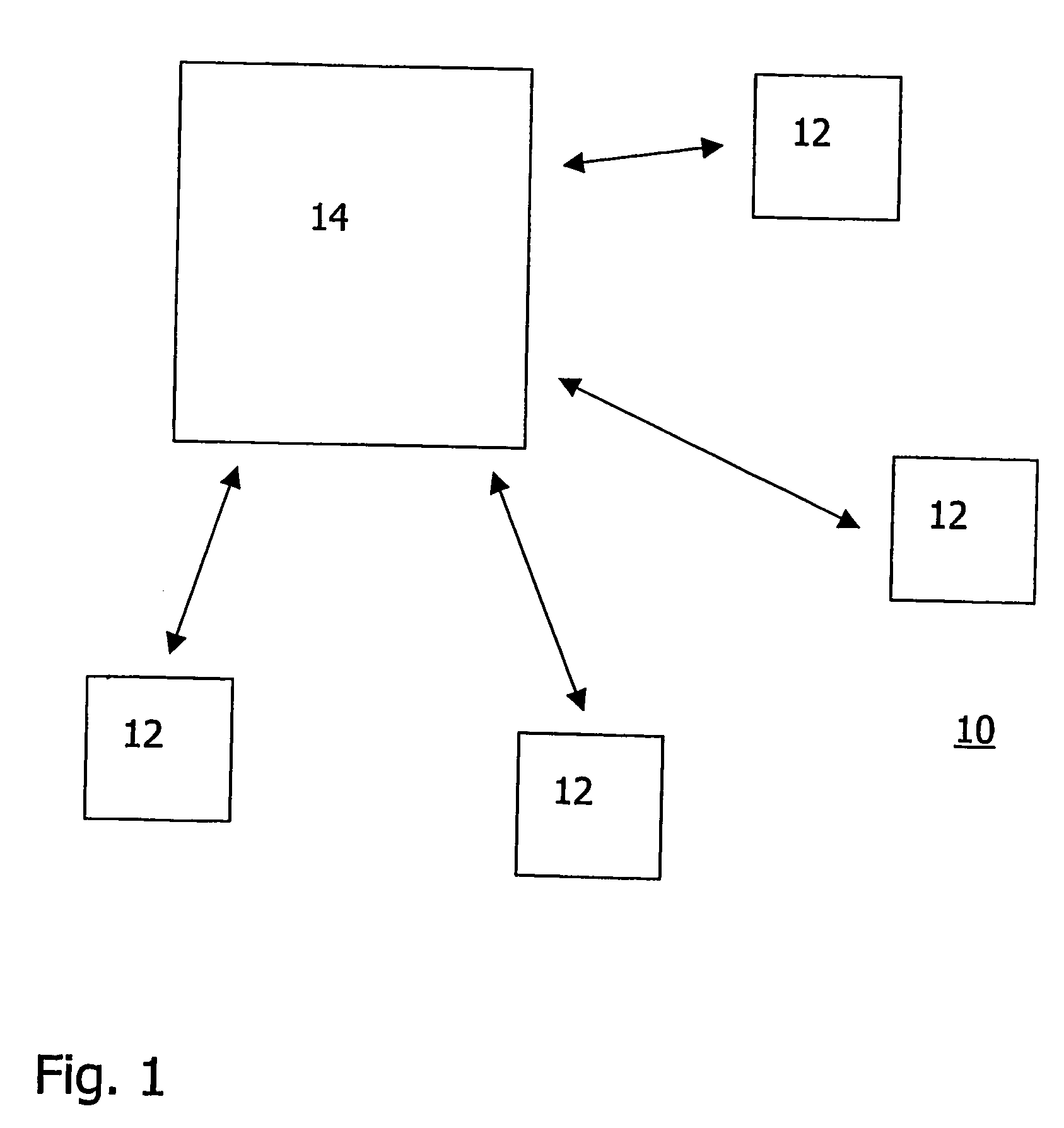
[0047] the BS 14 determines in a first step a particular network condition that can be influenced by means of a control of the advanced receiver structures 26, 28, 30, 32 of the UE 12. The network condition may be load of an individual cell serviced by the BS 14, in particular when there is a capacity problem in the cell.

[0048]The BS 14 has several possibilities to determine the load of a particular cell. In general, the cell load can easily be determined based on information that is anyway available at the BS 14.

[0049]One way to determine the cell load is admission control. Information obtained during admission control includes the total number of UEs serviced by the BS 14. A large number of UEs indicates that there might be a capacity problem.

[0050]A further parameter indicative of the cell load is the current transmit power of the BS 14. An indication of the cell load can for example be obtained by comparing the current transmit power with the maximum transmit power of the BS 14....

second embodiment

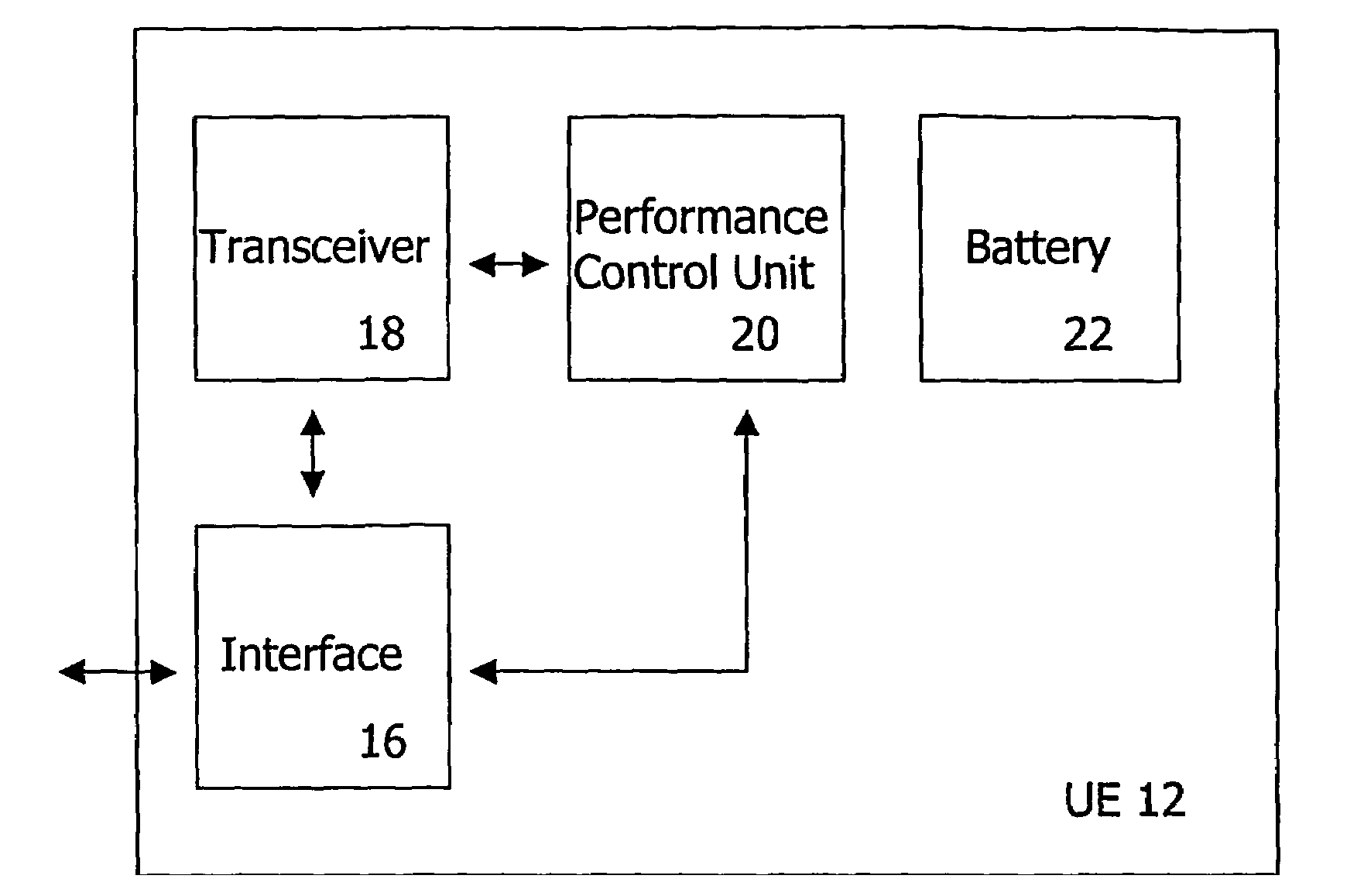
[0064]According to the invention, the UE 12 has an internal mechanism (not depicted in FIG. 2) for determining the cell load, the interference level or any other parameter indicative of a network condition. Like at the BS 14, such a parameter can be readily available so that in most cases no further hardware or software is needed for this purpose.

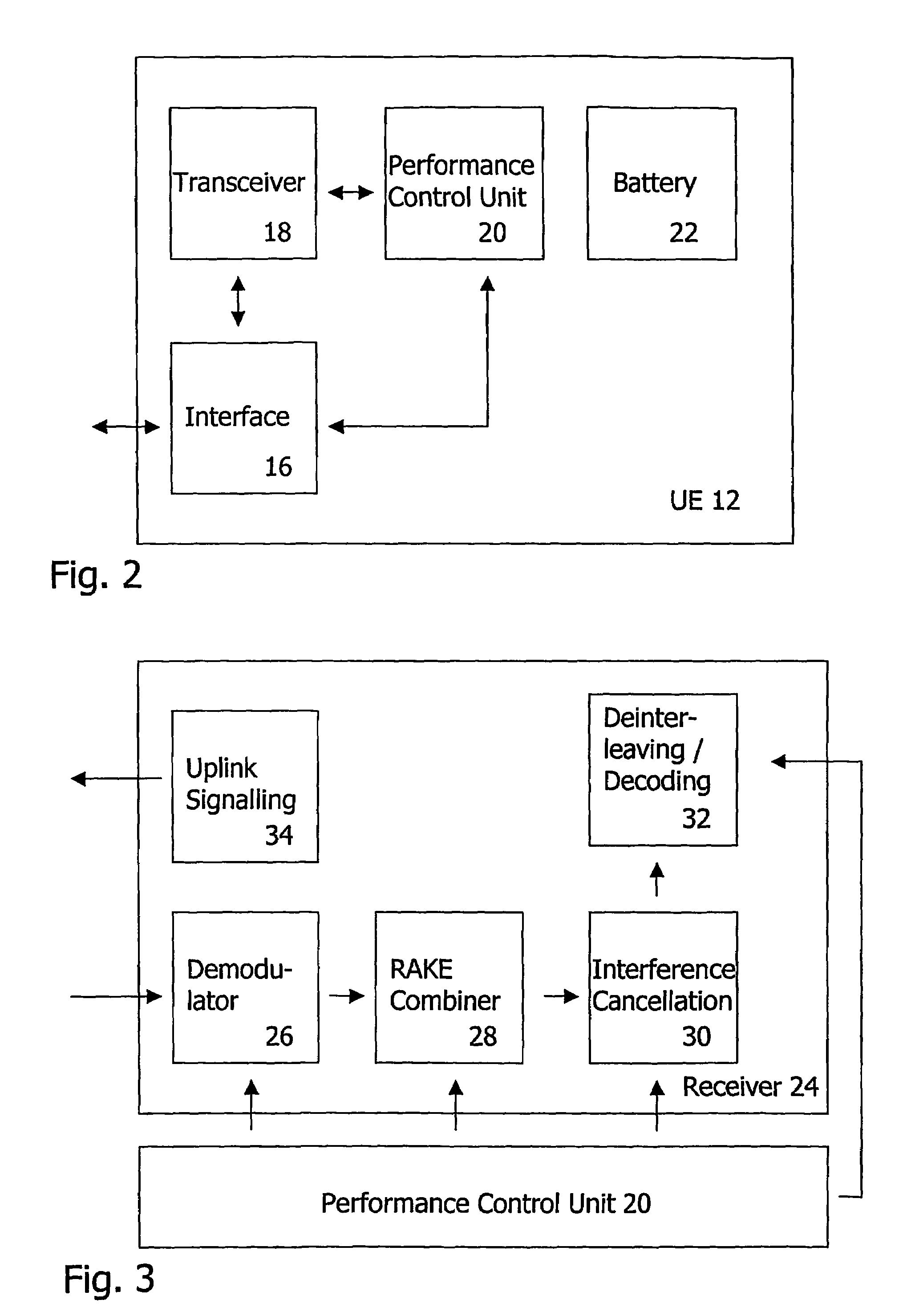
[0065]One possibility to determine the cell load within the UE 12 is to assess the reaction of the network to power control information that is sent uplink by the uplink signalling unit 34 depicted in FIG. 3. If for example the BS 14 does not increase its transmit power towards to UE 12 in response to one or more corresponding requests on uplink, the UE 12 can conclude that the cell load is high.

[0066]Once the cell load has been determined, the performance control unit 20 of the UE 12 decides whether or not one of the available advanced receiver structures 26, 28, 30, 32 shown in FIG. 3 are to change their state. If required, the performanc...


PUM


Abstract

A method of operating a network node that controls a component of a wireless communications network is described. The network component has a receiver with at least one receiver structure that can assume two or more states, including a first state corresponding to an enhanced receiver performance and a second state corresponding to a reduced receiver performance and a reduced power consumption. The method comprises determining a network condition and, in dependence of the network condition, generating a performance control signal that aims at controlling the state of the receiver structure, and transmitting the performance control signal to the network component. The invention is further directed the performance control signal generated by the network node and the network component which the network node intends to control.

Description

FIELD OF THE INVENTION[0001]The invention relates to wireless communications networks. More specifically, the invention relates to aspects in context with network components that have an enhanced receiver performance.BACKGROUND OF THE INVENTION[0002]Standardization is one of the key features of modern wireless communications networks. Thus, standardization documents like those issued by the 3rd Generation Partnership Project (3GPP) and the specifications defined therein have become of high importance to manufacturers of network infrastructure in general and manufacturers of network components like mobile terminals in particular.[0003]A central aspect of all standardization approaches are specific minimum requirements. Such minimum requirements insure a high compatibility among network components from different manufacturers. At the same time minimum requirements do not hinder the introduction of more sophisticated features for the benefit of network operators or network users.[0004]...

Claims


Application Information

Patent Timeline
Patent Type & Authority Patents(United States)
IPC IPC(8): H04B7/00H04B7/005H04B7/26H04B17/00H04W52/08H04W52/28H04W52/34
CPCH04W24/08H04W52/08H04W52/34H04W52/288Y02D30/70H04B7/005
Inventor SCHOTTEN, HANS DIETER
Owner TELEFON AB LM ERICSSON (PUBL)
Why Eureka
Try Eureka