Heat shield panels for use in a combustor for a gas turbine engine

Active Publication Date: 2006-08-22
RAYTHEON TECH CORP
View PDF35 Cites 167 Cited by
  • Summary
  • Abstract
  • Description
  • Claims
  • Application Information

AI Technical Summary

Benefits of technology

[0008]It is a further object of the present invention to prov

Problems solved by technology

Gas turbine engine combustors are generally subject to high thermal loads for prolonged periods of time.
A disadvantage of this cooling arrangement is that the necessary hardware includes a multiplicity of parts.
Specifically, internal components such as turbines and compressors can be susceptible to damage from foreign objects carried within the air flow through the engine.
A further disadvantage of the above described cooling arrangement is the overall weight which accompanies the multiplicity of parts.
A disadvan

Method used


Image

  • Heat shield panels for use in a combustor for a gas turbine engine
  • Heat shield panels for use in a combustor for a gas turbine engine
  • Heat shield panels for use in a combustor for a gas turbine engine

Examples


Embodiment Construction

)

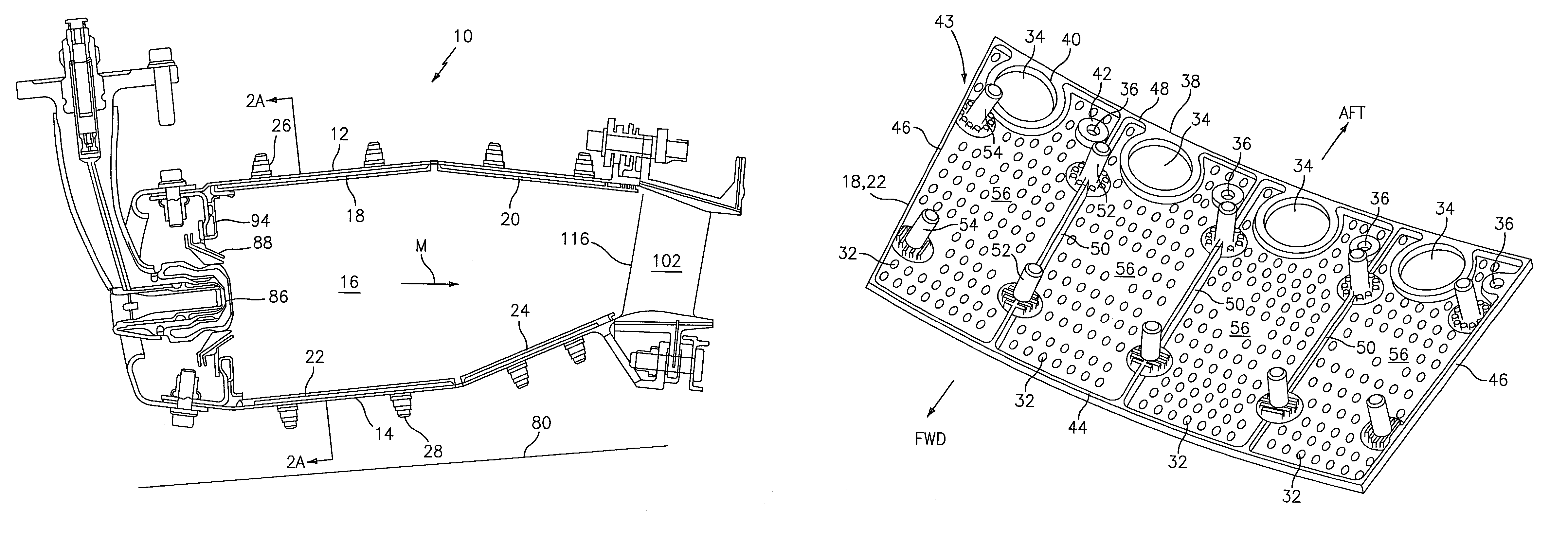
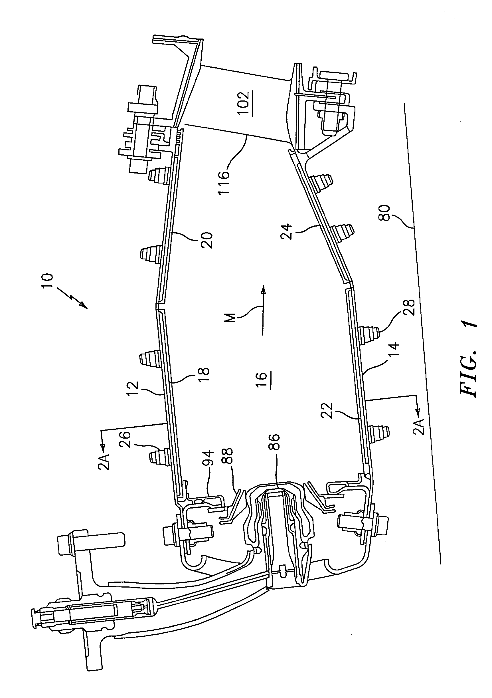
[0032]Referring now to FIG. 1, the combustor 10 for a gas turbine engine comprises a radially outer support shell 12 and a radially inner support shell 14. The support shells 12 and 14 define an annular combustion chamber 16. The combustion chamber has a mean combustor airflow in the direction M.

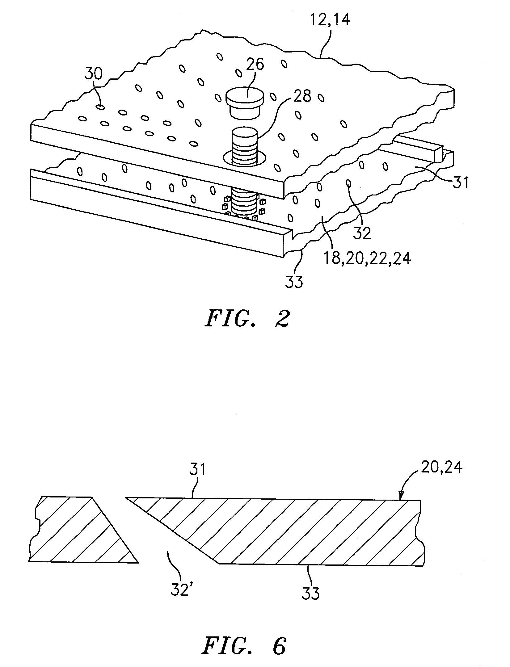
[0033]Heat shield panels or liners line the hot side of the inner and outer support shells 12 and 14. An array of forward heat shield panels 18 and an array of rear heat shield panels 20 line the hot side of the outer support shell 12, while an array of forward heat shield panels 22 and an array of rear heat shield panels 24 line the hot side of the inner support shell 14. Nuts 26 and bolts 28 may be used to connect each of the heat shield panels 18, 20, 22, and 24 to the respective inner and outer support shells 14 and 12.

[0034]As shown in FIG. 2, impingement cooling holes 30 penetrate through each of the inner and outer support shells 14 and 12 to allow a coolant, such as air, to enter th...


PUM


Abstract

The present invention relates to heat shield panels or liners to be used in combustors for gas turbine engines. The heat shield panels each comprise a hot side and a cold side and at least one isolated cooling chamber on the cold side. Each cooling chamber has a plurality of cooling film holes for allowing a coolant, such as air, to flow from the cold side to the hot side. A combustor having an arrangement of heat shield panels or liners is also described.

Description

BACKGROUND OF THE INVENTION[0001]The present invention relates to combustors for gas turbine engines in general, and to heat shield panels for use in double wall gas turbine combustors in particular.[0002]Gas turbine engine combustors are generally subject to high thermal loads for prolonged periods of time. To alleviate the accompanying thermal stresses, it is known to cool the walls of the combustor. Cooling helps to increase the usable life of the combustor components and therefore increase the reliability of the overall engine.[0003]In one cooling embodiment, a combustor may include a plurality of overlapping wall segments successively arranged where the forward edge of each wall segment is positioned to catch cooling air passing by the outside of the combustor. The forward edge diverts cooling air over the internal side, or hot side, of the wall segment and thereby provides film cooling for the internal side of the segment. A disadvantage of this cooling arrangement is that the...

Claims


Application Information

Patent Timeline
IPC IPC(8): F02C1/00F02G3/00F23R3/42F23R3/00F23R3/06F23R3/60
CPCF23R3/002F23R3/06F23R3/60F23R2900/03042F23R2900/03041
Inventor PACHECO-TOUGAS, MONICACOUGHLAN, III, JOSEPH D.HOKE, JAMES B.GOETSCHIUS, ALAN J.
Owner RAYTHEON TECH CORP
Why Eureka
Try Eureka