Configurable vibration sensor

Inactive Publication Date: 2006-08-22
MECHWORKS SYST
View PDF14 Cites 651 Cited by
  • Summary
  • Abstract
  • Description
  • Claims
  • Application Information

AI Technical Summary

Problems solved by technology

Changes in the oscillation form of vibrations emanating from such machinery can result from a simple change in operation, but they may also be the result of wear, failure or fatigue of mechanical parts.

Method used


Image

  • Configurable vibration sensor
  • Configurable vibration sensor
  • Configurable vibration sensor

Examples


Embodiment Construction

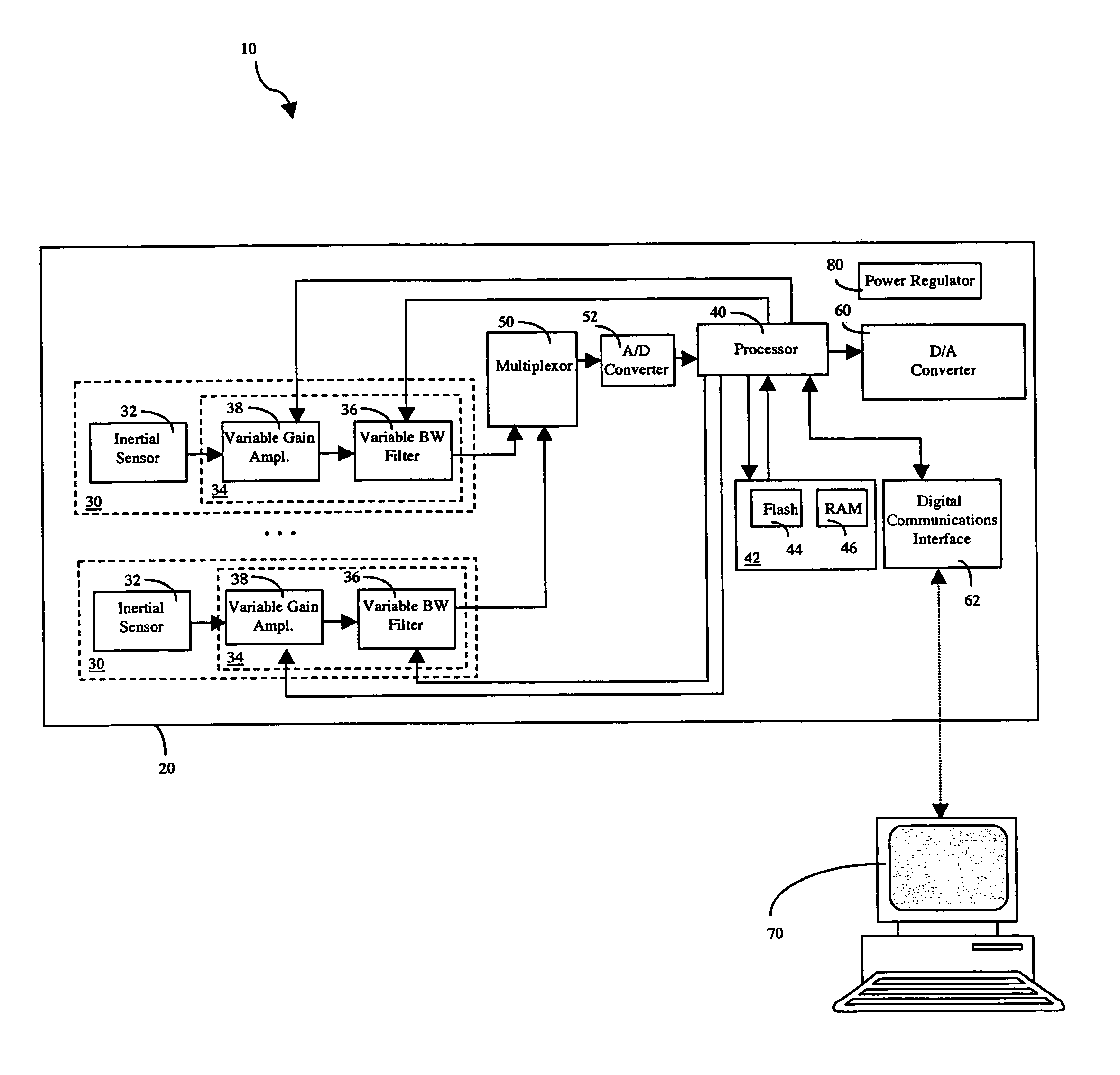
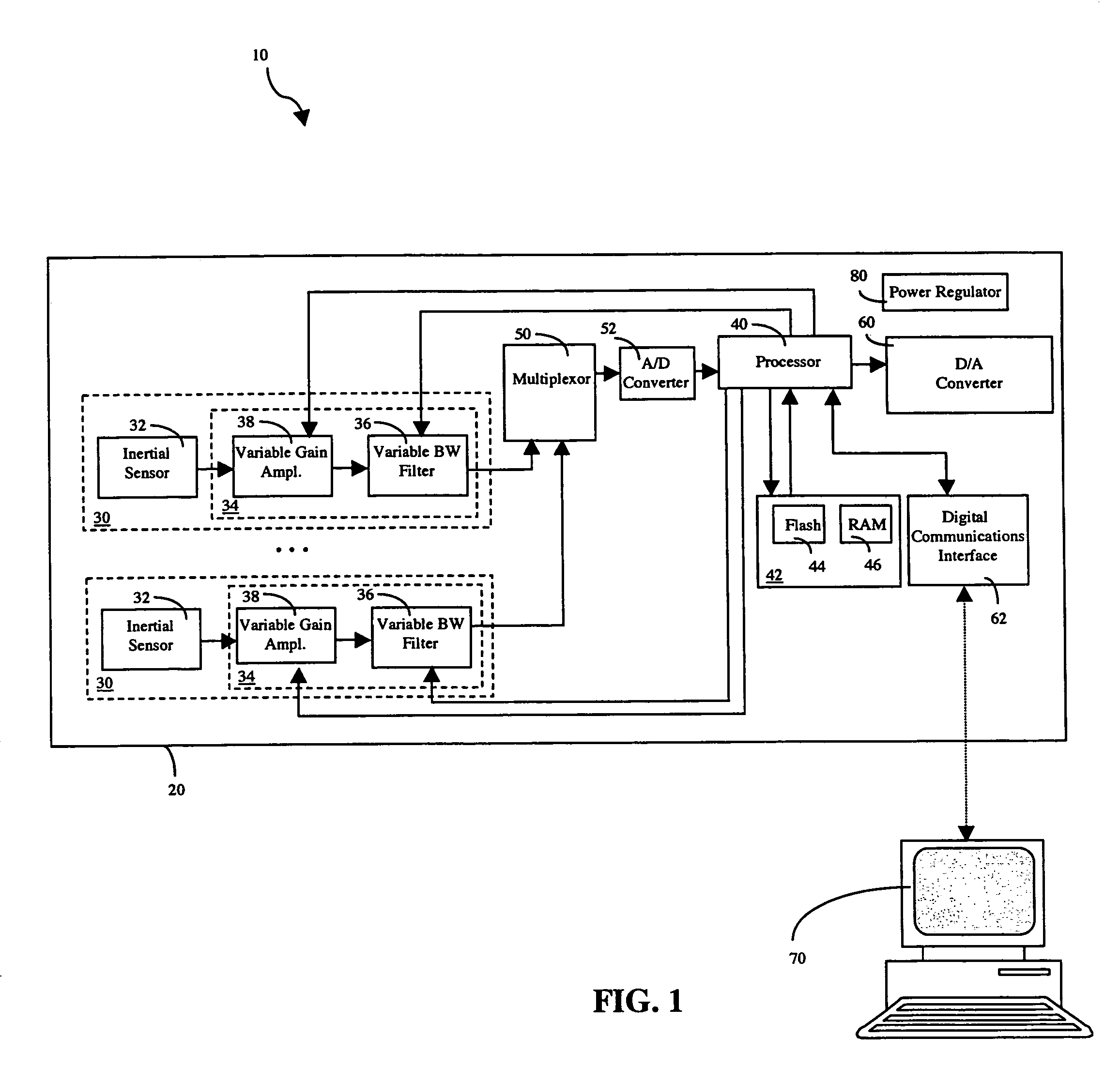
[0024]Embodiments of the invention are directed to vibration sensors for detecting vibrations in vibrating structures such as machinery and the like. These vibration sensors are referred to herein as configurable vibration sensors, as they can be configured for different vibration measurement applications. For example, an accelerometer attached to a bearing housing would require a large bandwidth to observe vibrations due to the bearing itself, while the same sensor could also be used to monitor oscillations or sway in a machine that includes the previously mentioned bearing housing using a much smaller bandwidth.

[0025]The term “configure” and derivations thereof as used in the specification and in the claims is not restricted to meaning that such action may only be performed once. For example, in some embodiments of the invention, the configuration of a vibration sensor may be set only once, while in other embodiments of the invention, the configuration of a vibration sensor may be...


PUM

PropertyMeasurementUnit
frequencyaaaaaaaaaa
poweraaaaaaaaaa
mechanical structureaaaaaaaaaa

Abstract

A configurable vibration sensor having a sensor circuit, an analog-to-digital converter and a processor is provided. The sensor circuit employs a vibration sensing element and a variable bandwidth filter controllable by the processor. In addition to the variable bandwidth filter, other configurable elements may also be employed in the sensor circuit, including a variable gain amplifier. These configurable elements allow the configurable vibration sensor to be configured for different vibration measurement applications when measuring vibrations from vibrating structures such as machinery and the like.

Description

FIELD OF THE INVENTION[0001]Embodiments of the invention relate generally to vibration sensors for use with vibrating structures such as machinery and the like, and more specifically to vibration sensors that can be configured for different vibration measurement applications.BACKGROUND OF THE INVENTION[0002]Machines and other vibrating structures generate characteristic vibrations during their normal operations. These vibrations can vary from a simple sinusoidal type, to a complex, multi-frequency, non-linear oscillation or random type. Changes in the oscillation form of vibrations emanating from such machinery can result from a simple change in operation, but they may also be the result of wear, failure or fatigue of mechanical parts. By analyzing and isolating the characteristics of the vibrations of a machine, early warning signs of machine failures can be detected. This information may be used to prevent unscheduled downtime of the machine, thereby increasing machine efficiency....

Claims


Application Information

Patent Timeline
Patent Type & Authority Patents(United States)
IPC IPC(8): G01H1/00G01N29/00G01N29/14G01N29/40G01N29/42G01N29/46
CPCG01N29/14G01N29/46G01N29/42G01N29/40
Inventor TREIBER, MARKMCCLELLAN, CHRISTOPHERGOLNARAGHI, FARID
Owner MECHWORKS SYST
Why Eureka
Try Eureka