
Pipette control arrangement

a control arrangement and pipette technology, applied in the field of nonmotorized or manually operated pipette control arrangements, can solve the problems of undesirable or unsuitable specific use, inability to rapidly disperse large volumes of liquid, and prior art pipette control arrangements

Active Publication Date: 2006-08-22
BEL ART PRODS
View PDF25 Cites 2 Cited by
  • Summary
  • Abstract
  • Description
  • Claims
  • Application Information

AI Technical Summary

Benefits of technology

[0006]Accordingly, it is an object of the present invention to provide a pipette control arrangement which is relatively simple in construction and that is capable of accommodating a plurality of cylinder-plunger assemblies having a varying volume capacity.
[0007]It is a further object of the invention to provide a pipette control arrangement that includes a quick release mechanism for rapidly introducing air into and or releasing an existing vacuum in the pipette control system, which allows for the rapid discharge of any liquid present in the pipette.
[0008]Still further, it is an object of the invention to provide a pipette control arrangement that includes a simply and inexpensively constructed housing that allows quick and efficient access by an operator to replace or swap out one or more or all of the components of the pipette control system.
[0014]As to still another aspect of the invention, the pipette control arrangement includes a quick release spring biased trigger mechanism operatively connected to the pump assembly for rapidly introducing air into and or releasing an existing vacuum pressure in the pipette connecting system, which allows for the rapid discharge of any liquid present in the pipette.
[0017]According to still a further aspect of the invention, a pipette control arrangement is provided for controlling the volumetric aspiration and or dispensing of liquid by a pipette. The pipette control arrangement includes a housing assembly that includes a neck portion and a handle portion, a pipette connector assembly, for removably connecting a pipette, a pump assembly that is equipped to independently accommodate one of a plurality of volume specific removably connected cylinder-plunger assemblies and an air tube connected between the pipette connector assembly and the pump housing. The pipette control arrangement further includes a flexible pipette connector and a quick release spring biased trigger mechanism for rapidly introducing air into and or releasing an existing vacuum pressure in the flexible pipette connector, thereby allowing for the rapid discharge of any liquid present in the pipette.

Problems solved by technology

The pipette control arrangements of the prior art, however, generally suffer from one or more drawbacks and limitations that oftentimes render them undesirable or unsuitable for a specific use.
Generally these drawbacks and limitations stem from the device being unable to efficiently accommodate a wide variety of volumes of liquid and are therefore limited to certain pipettes having specific volumetric capacities.
Furthermore, these devices suffer from the inability to rapidly dispense large volumes of liquid.
It would be obvious that this device is limited to a certain volume of liquid that may be aspirated and or dispensed by a pipette based upon the dimensions of the bellows pumping system.

Method used


Image

  • Pipette control arrangement
  • Pipette control arrangement
  • Pipette control arrangement

Examples


Embodiment Construction

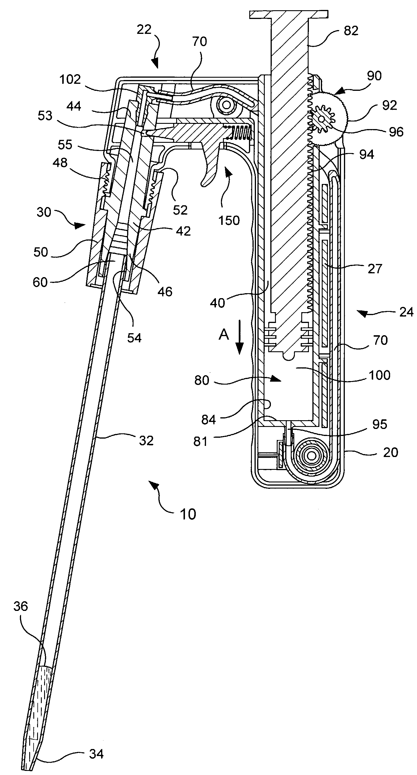
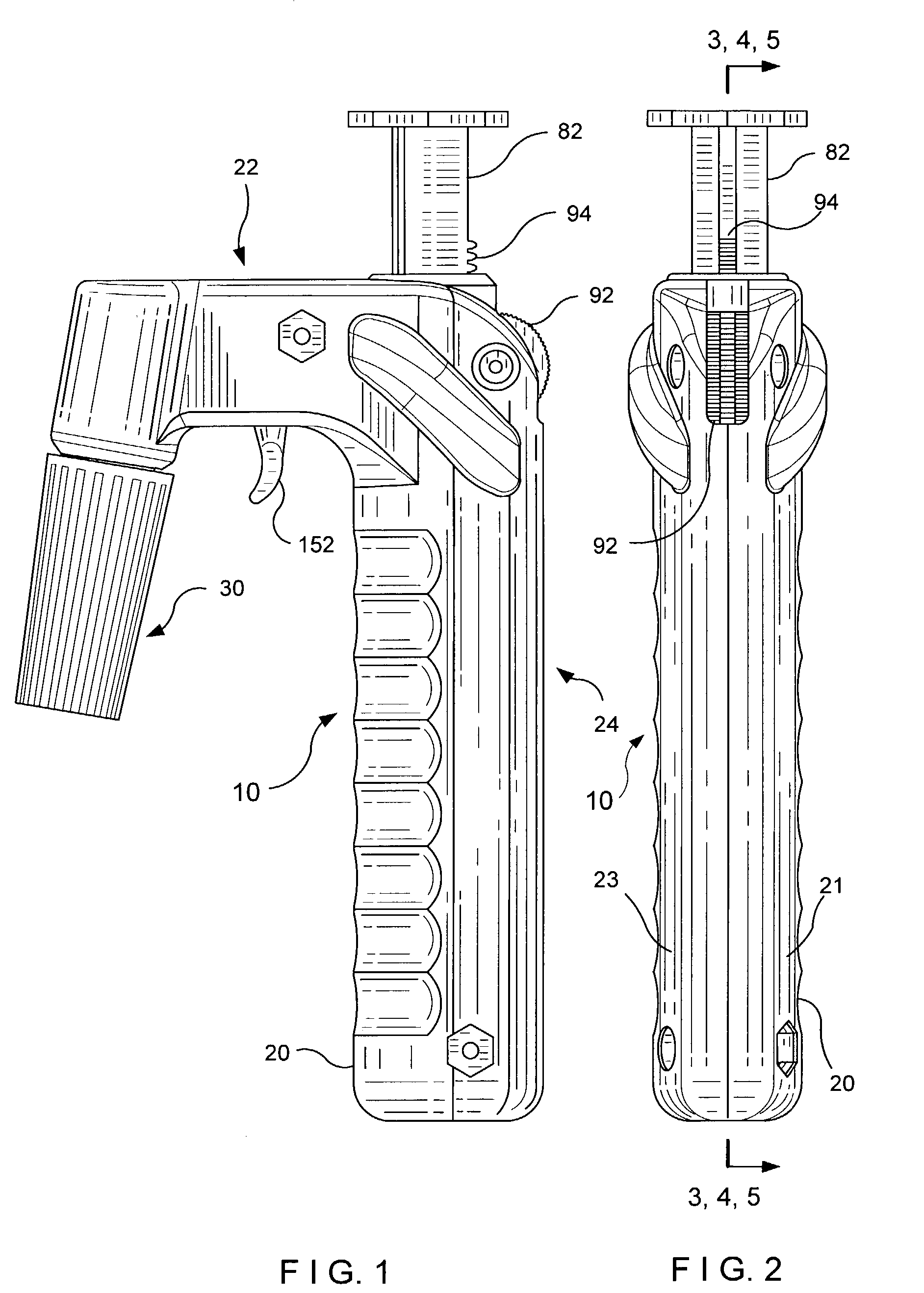
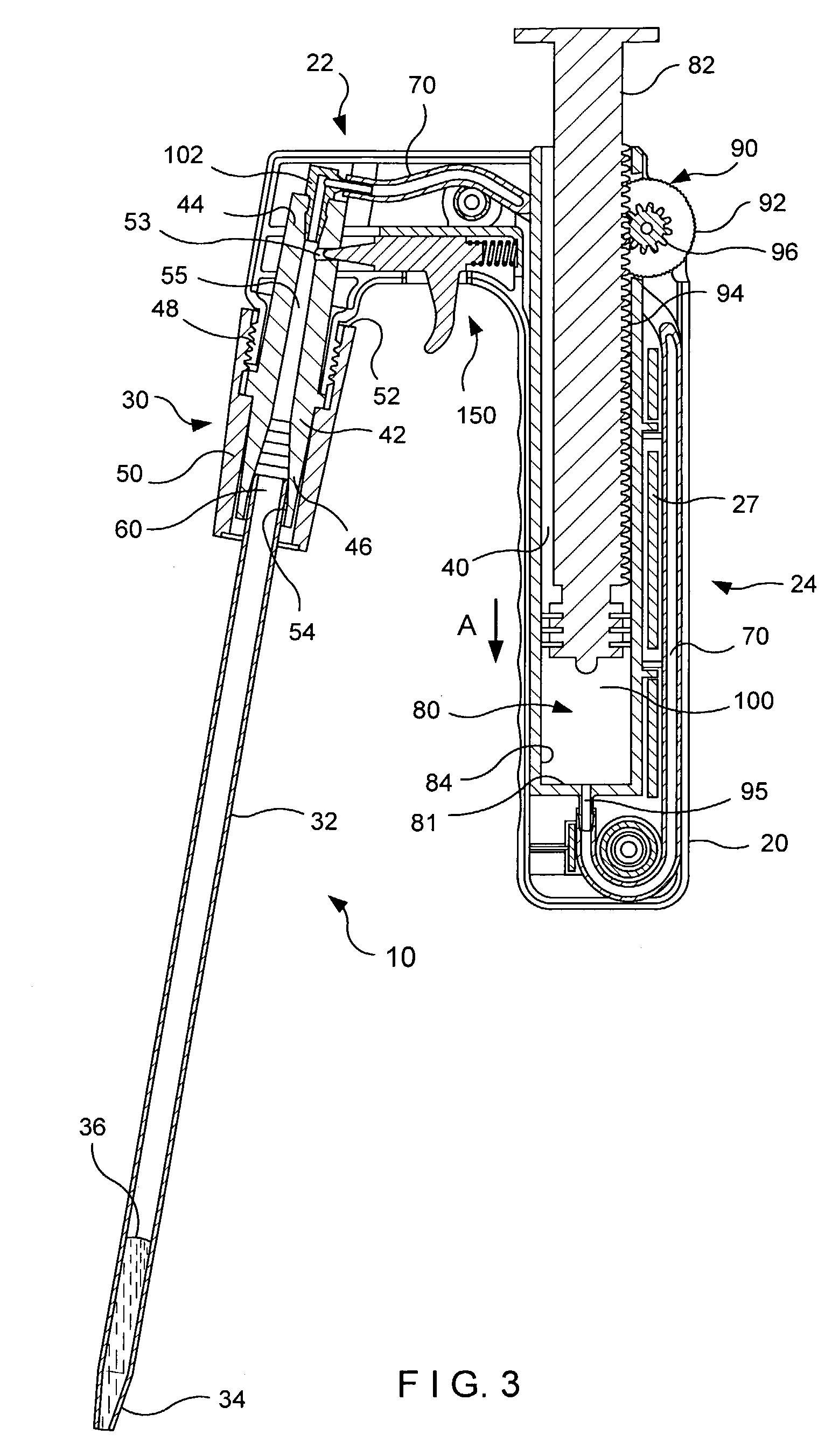
[0031]For purpose of illustration only, and not to limit generally, the present invention will now be described with specific reference to FIGS. 1–12. It is noted that the drawings of the invention are intended to depict only typical embodiments of the invention, are not necessarily to scale and are merely schematic representations, not intended to portray specific controller parameters on the invention. The invention will now be described with additional specificity and detail through the accompanying drawings.

[0032]With reference to the Figures, wherein like numerals reference like or corresponding parts throughout the several views, FIGS. 1–3 show a representative embodiment of a pipette control arrangement 10, which is adapted to facilitate accurate pipetting of liquids. The pipette control arrangement 10 includes a housing assembly 20, which is preferably molded of a plastic material and which is preferably formed having a substantially inverted L-shaped configuration with a pi...


PUM

PropertyMeasurementUnit
volumeaaaaaaaaaa
volumeaaaaaaaaaa
volumeaaaaaaaaaa

Abstract

A pipette control arrangement consists of a housing assembly adapted for operatively housing a pump assembly and for operatively connecting a pipette to the pump assembly via a flexible air tube. The pump assembly is adapted to independently accommodate a plurality of volume specific removable cylinder-plunger systems. The pipette control arrangement may further include a quick release trigger operated mechanism for rapidly and or in large volumes dispensing liquid from an attached pipette.

Description

FIELD OF THE INVENTION[0001]The present invention relates to the field of non-motorized or manually operated pipette control arrangements, and more particularly, to pipette control arrangements capable of accommodating a range of volumetric capacities, pipetting speeds and pipetting accuracy requirements.BACKGROUND OF THE INVENTION[0002]A typical non-motorized or manually operated pipette control arrangement includes a housing that incorporates a pumping system and a pipette connecting mechanism for either fixedly of removably connecting a pipette to the housing. Some of these arrangements include a thumb operated mechanical system for controlling the aspiration and dispensing of liquids by the pipette.[0003]Various prior art pipette control arrangements exist and are effective in aspirating and dispensing liquids through a pipette. The pipette control arrangements of the prior art, however, generally suffer from one or more drawbacks and limitations that oftentimes render them unde...

Claims


Application Information

Patent Timeline
Patent Type & Authority Patents(United States)
IPC IPC(8): G01N1/00B01L3/02
CPCB01L3/0213B01L3/0217B01L2400/0694B01L2400/0633B01L2200/087B01L3/02
Inventor THOM, PAULHARRISON, DOUGLAS W.GOMES, FRANCISLANDSBERGER, DAVID
Owner BEL ART PRODS
Learn More