Liquid pumping device

a technology of liquid pumping device and pumping chamber, which is applied in the direction of liquid handling, positive displacement liquid engine, packaging goods type, etc., can solve the problems of manual work and work time waste, and achieve the effect of enhancing the versatility of the liquid pumping devi

Active Publication Date: 2006-08-22
YO LEE MFG
View PDF2 Cites 30 Cited by
  • Summary
  • Abstract
  • Description
  • Claims
  • Application Information

AI Technical Summary

Benefits of technology

[0011]The primary objective of the present invention is to provide a liquid pumping device that is operated automatically and manually, thereby greatly enhancing the versatility of the liquid pumping device.
[0012]Another objective of the present invention is to provide a liquid pumping device that is operated automatically by the power source to suck the liquid from the suction pipe into the inside of the barrel rapidly.
[0013]A further objective of the present invention is to provide a liquid pumping device that is operated manually by the operation lever to suck the liquid from the suction pipe into the inside of the barrel rapidly.

Problems solved by technology

However, the conventional liquid pumping device is operated manually by press lever to suck the liquid from the suction pipe into the inside of the cylinder, thereby wasting the manual work and the working time.

Method used


Image

  • Liquid pumping device
  • Liquid pumping device
  • Liquid pumping device

Examples


Embodiment Construction

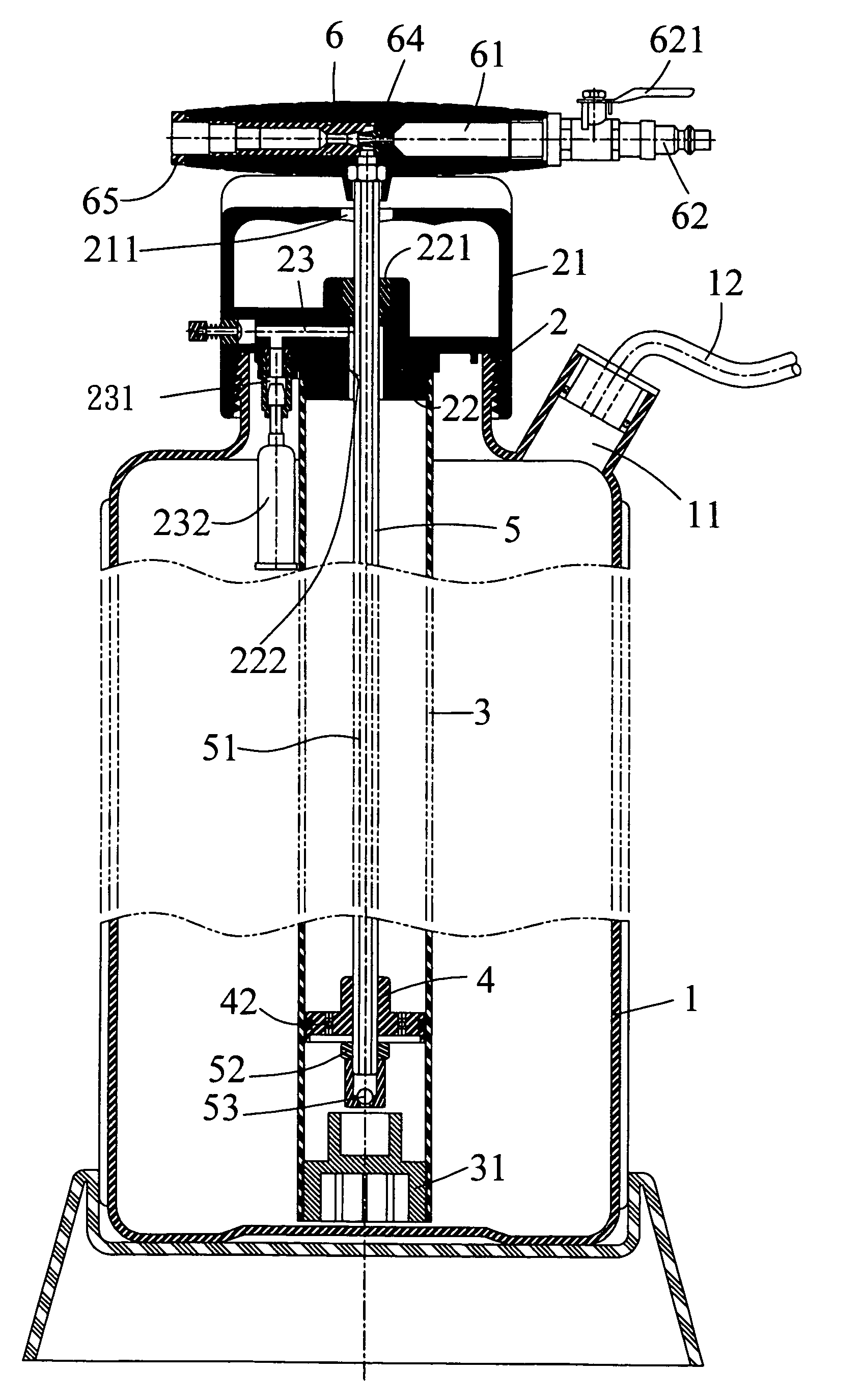
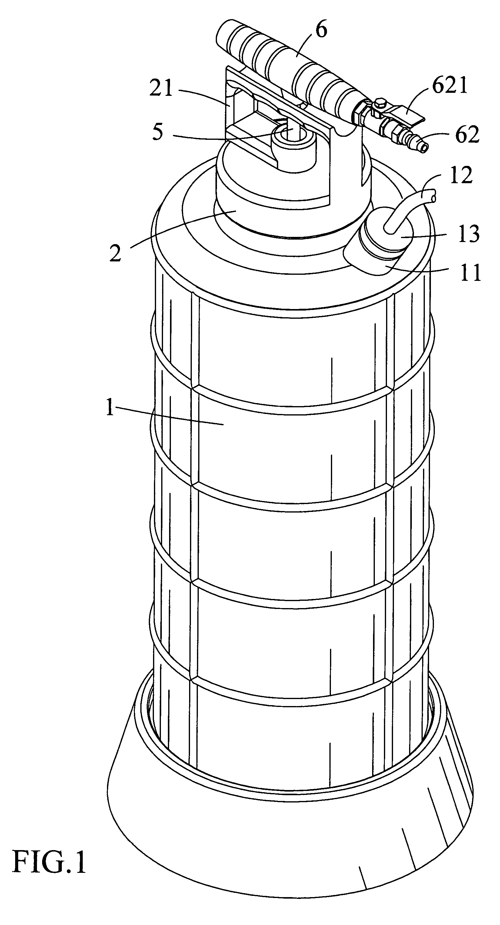
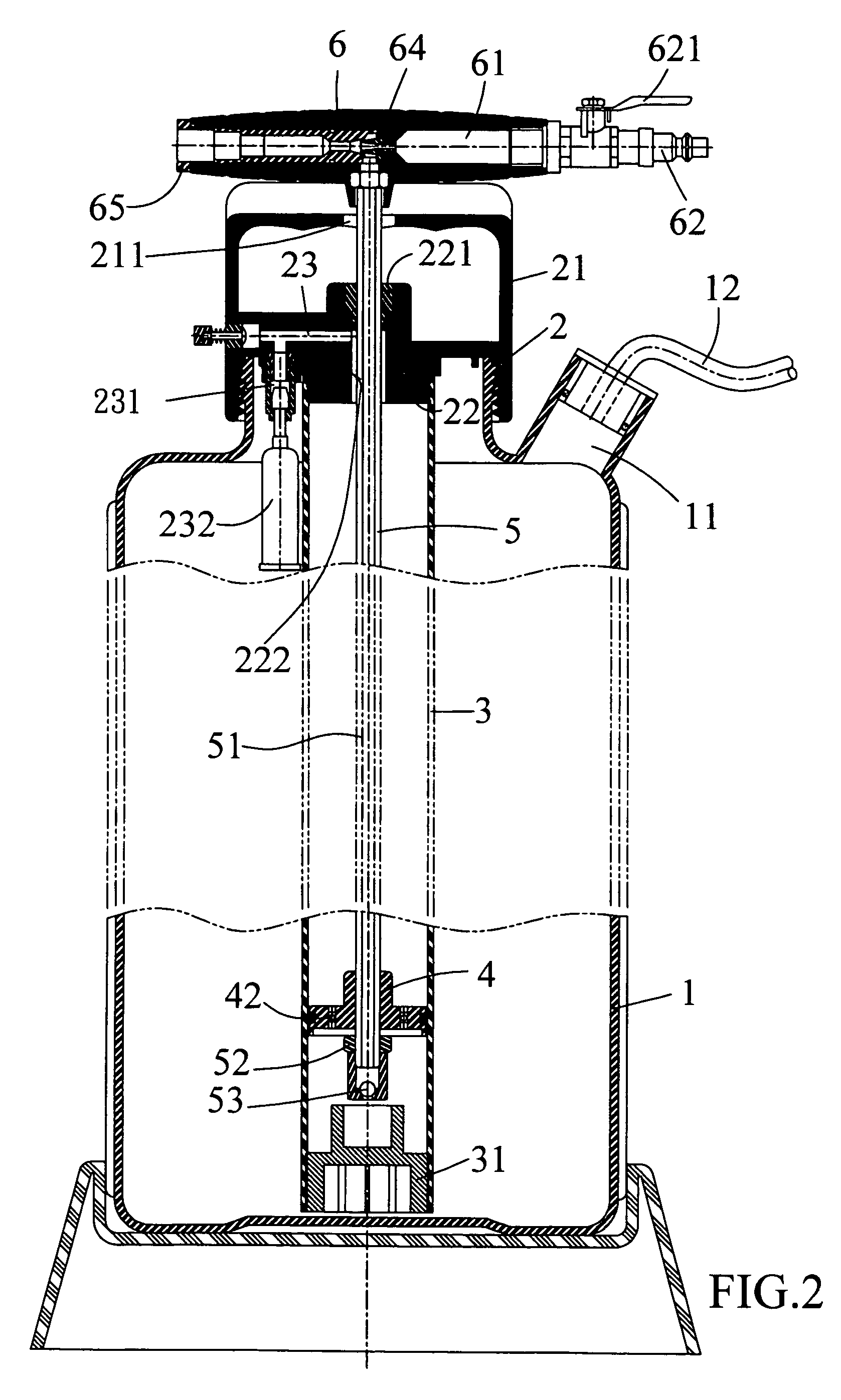
[0022]Referring to the drawings and initially to FIGS. 1–4, a liquid pumping device in accordance with the preferred embodiment of the present invention comprises a barrel 1, a cylinder 3, a conducting rod 5, a piston 4, an operation lever 6, and a cover 2.

[0023]The barrel 1 has a top formed with a suction hole 11 for mounting a suction pipe 12 which is mounted in the suction hole 11 of the barrel 1 by a seal 13.

[0024]The cylinder 3 is mounted in the barrel 1. A sealing ring 31 is mounted on a lower end of the cylinder 3.

[0025]The conducting rod 5 is movably mounted in the cylinder 3 and has an upper end protruding outward from the barrel 1. The conducting rod 5 has an inside formed with a conducting hole 51 and has a lower end provided with a oneway valve 53 to allow fluid in the cylinder 3 to flow upward into the conducting hole 51 only.

[0026]The piston 4 is movably mounted in the cylinder 3 and is secured on the lower end of the conducting rod 5 to move therewith. The piston 4 ha...


PUM

PropertyMeasurementUnit
dimensionaaaaaaaaaa
elasticaaaaaaaaaa
conductingaaaaaaaaaa

Abstract

A liquid pumping device includes a barrel, a cylinder, a conducting rod, a piston, an operation lever, and a cover. Thus, the liquid pumping device is operated automatically by the power source or operated manually by the operation lever to suck the liquid from the suction pipe into the inside of the barrel rapidly, so that the liquid pumping device is operated automatically and manually, thereby greatly enhancing the versatility of the liquid pumping device.

Description

BACKGROUND OF THE INVENTION[0001]1. Field of the Invention[0002]The present invention relates to a liquid pumping device, and more particularly to a liquid pumping device that is operated automatically and manually, thereby enhancing the versatility of the liquid pumping device.[0003]2. Description of the Related Art[0004]A conventional liquid pumping device comprises a cylinder, a suction pipe connected to the cylinder, a piston movably mounted in the cylinder, a movable rod movably mounted in the cylinder and having a lower end secured to the piston to push the piston, and a press lever mounted on the movable rod to move the movable rod. Thus, the press lever is pulled upward and pushed downward to move the piston in the cylinder reciprocally, thereby forming a vacuum suction in the inside of the cylinder so as to suck a liquid, such as the oil or the like, from the suction pipe into the inside of the cylinder. However, the conventional liquid pumping device is operated manually b...

Claims


Application Information

Patent Timeline
Patent Type & Authority Patents(United States)
IPC IPC(8): B65B31/04
CPCF04B33/00F04F5/20F04F3/00Y10T137/3109
Inventor CHEN, CHI-LIANG
Owner YO LEE MFG
Why Eureka
Try Eureka