Belt conveyor

a belt conveyor and belt technology, applied in the field of belt conveyors, can solve the problems of unsuitable roller conveyors and unsuitable belt conveyors in certain applications, and achieve the effect of not being suitable for belt conveyors and roller conveyors

Inactive Publication Date: 2006-08-22
DEMATIC
View PDF43 Cites 27 Cited by
  • Summary
  • Abstract
  • Description
  • Claims
  • Application Information

AI Technical Summary

Benefits of technology

[0017]Therefore, the present invention provides a belt conveyor which may have a plurality of independently operable zones or segments, each of which includes a continuous conveyor belt driven by a motorized roller. The zones may operate together as a generally continuously running belt conveyor or may operate individually as an accumulating conveyor with zone control and photo eyes or sensors. The present invention thus provides a zone controlled belt conveyor which may operate in a similar manner as a zone controlled roller conveyor, but with a conveyor belt reeved around the motorized roller and idler rollers rather than with multiple O-rings or the like connecting the idler rollers to the motorized roller of each zone. The belt conveyor of the present invention thus is capable of accumulating articles on an incline or decline. Because the motorized roller of each zone may only control or drive a small belt section or zone, the load and wear on the motorized roller is minimized to provide a longer life cycle for the motorized roller.
[0018]The angled conveyor section of the present invention provides a substantially continuous, belted conveying surface at an angle for abutting or mating against a conveying or transport path. The angled conveyor section includes a motorized roller which is operable to drive the different length rollers of the angled conveyor section via a plurality of different length belt strips reeved around the motorized roller and the different length rollers of the conveyor section. The angled conveyor section of the present invention thus provides a powered or motorized roller and a belt conveying surface which does not require special routing of the belt underneath the angled section to align the belt with the angled mating surface or edge.

Problems solved by technology

However, such roller conveyors are not suitable for certain applications where belt conveyors are desired, such as for conveying small articles which may fall between the rollers or for applications where a belt conveyor may be required or desired for other reasons.
Also, due to the low friction between the rollers and the articles being conveyed thereon, such roller conveyors are not suitable for providing accumulation of articles along an inclined or declined section of the roller conveyor.
However, such angled belted conveyor sections typically include complicated routing paths for the belt beneath the conveyor section to properly align and track the belt around an end roller at the angled mating edge of the angled belted conveyor section.

Method used


Image

  • Belt conveyor
  • Belt conveyor
  • Belt conveyor

Examples


Embodiment Construction

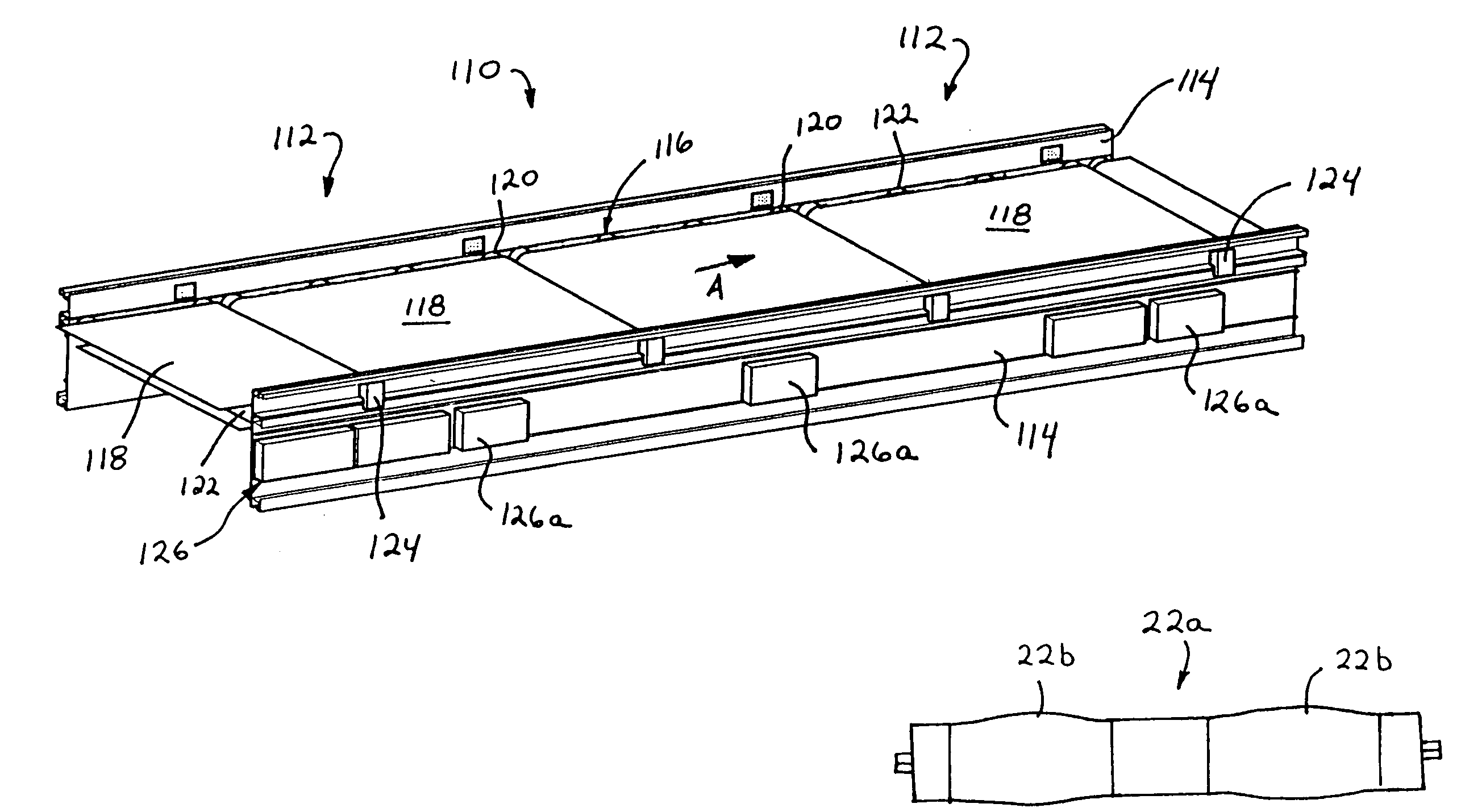
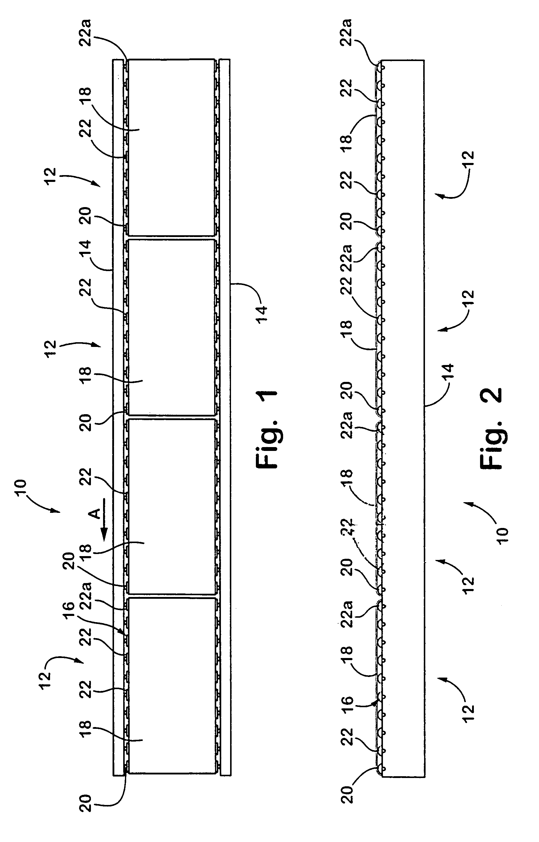
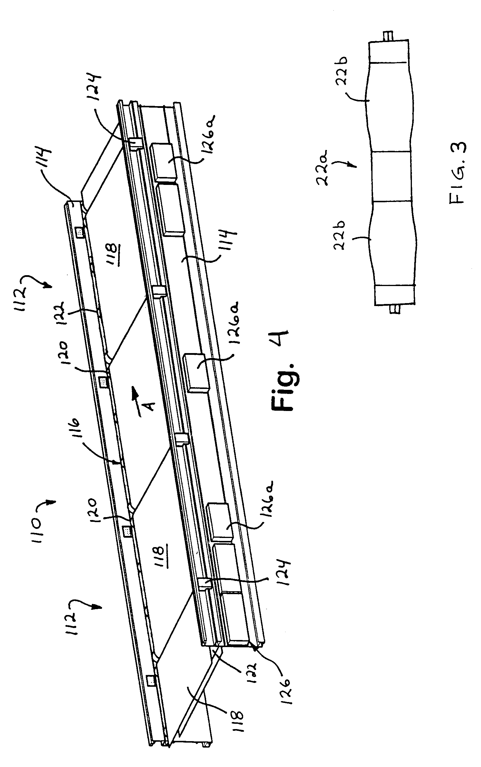
[0032]Referring now specifically to the drawings and the illustrative embodiments depicted therein, a belt conveyor or belt accumulator 10 includes one or more zones or segments 12 positioned along and between opposite sidewalls or side frames 14, and is operable to convey articles in a direction of conveyance A (FIGS. 1 and 2). Each segment or zone 12 includes a plurality of rollers 16 and a continuous belt 18 routed or reeved around the rollers 16. Each belted segment 12 may be independently operable to accumulate articles on the segment or zone or to move articles in the direction A onto a next, adjacent segment or zone or onto another conveyor, such as another belt conveyor, a roller conveyor, a slider bed, or the like, or any other means for receiving articles from a discharge end of the last zone or segment of the segmented belt conveyor 10. As best seen in FIG. 1, belt 18 may be wide enough to substantially cover the generally cylindrical roller portions of the rollers and th...


PUM


Abstract

A belt conveyor or belt accumulator includes at least two tandem zones, each of which is defined by a motorized roller and at least one idler roller positioned along and between opposite sidewalls of the conveyor and a continuous belt routed around the motorized roller and the idler roller or rollers. The motorized roller is operable to drive the belt around the rollers to move articles along the respective zone. The belt may have a low modulus characteristic and may be initially stretched at least 0.75% in its lengthwise direction when the belt is reeved or routed around the rollers. The motorized roller of each zone may be independently operable, such as in response to an article sensor at each zone, to convey or accumulate articles on the respective zone of the belt conveyor.

Description

CROSS-REFERENCE TO RELATED APPLICATIONS[0001]The present application is a division of U.S. patent application, Ser. No. 10 / 358,690, filed Feb. 5, 2003 by Cotter et al., now U.S. Pat. No. 6,811,018, which claims priority of U.S. provisional applications, Ser. No. 60 / 356,045, filed Feb. 11, 2002 by Cotter et al., and Ser. No. 60 / 424,629, filed Nov. 7, 2002 by Cotter, which are hereby incorporated herein by reference in their entireties.FIELD OF THE INVENTION[0002]The present invention relates generally to conveyors and, more particularly, to belt conveyors. The present invention also relates generally to angled conveyor sections which are positioned at an angle with respect to a conveyor or transport system to induct or discharge articles onto or off from the conveyor or transport system.BACKGROUND OF THE INVENTION[0003]It is known to provide zones of rollers along a roller conveyor, where each zone includes a motorized roller and a plurality of idler or freely rotating rollers. The m...

Claims


Application Information

Patent Timeline
Patent Type & Authority Patents(United States)
IPC IPC(8): B65G23/04B65G15/22B65G15/12B65G15/24B65G15/30B65G15/32B65G15/50B65G15/64B65G39/02B65G39/071B65G43/00B65G43/10B65G47/26B65G47/31B65G47/53
CPCB65G15/22B65G15/24B65G15/32B65G15/50B65G15/64B65G39/071B65G43/10B65G47/261B65G47/31B65G47/53B65G39/02B65G2203/044
Inventor COTTER, DAVID HKOOISTRA, KENNETH JLEMAY, CURTIS E
Owner DEMATIC
Why Eureka
Try Eureka