
Radiometer with digital imaging system

a digital imaging and radiometer technology, applied in the field of radiometers with digital imaging systems, can solve problems such as sketchy documentation

Inactive Publication Date: 2006-08-22
RAYTEK
View PDF7 Cites 46 Cited by
  • Summary
  • Abstract
  • Description
  • Claims
  • Application Information

AI Technical Summary

Problems solved by technology

However, with current systems documentation can be sketchy and a serviceman or technician is required to document the measurements in a separate location.

Method used


Image

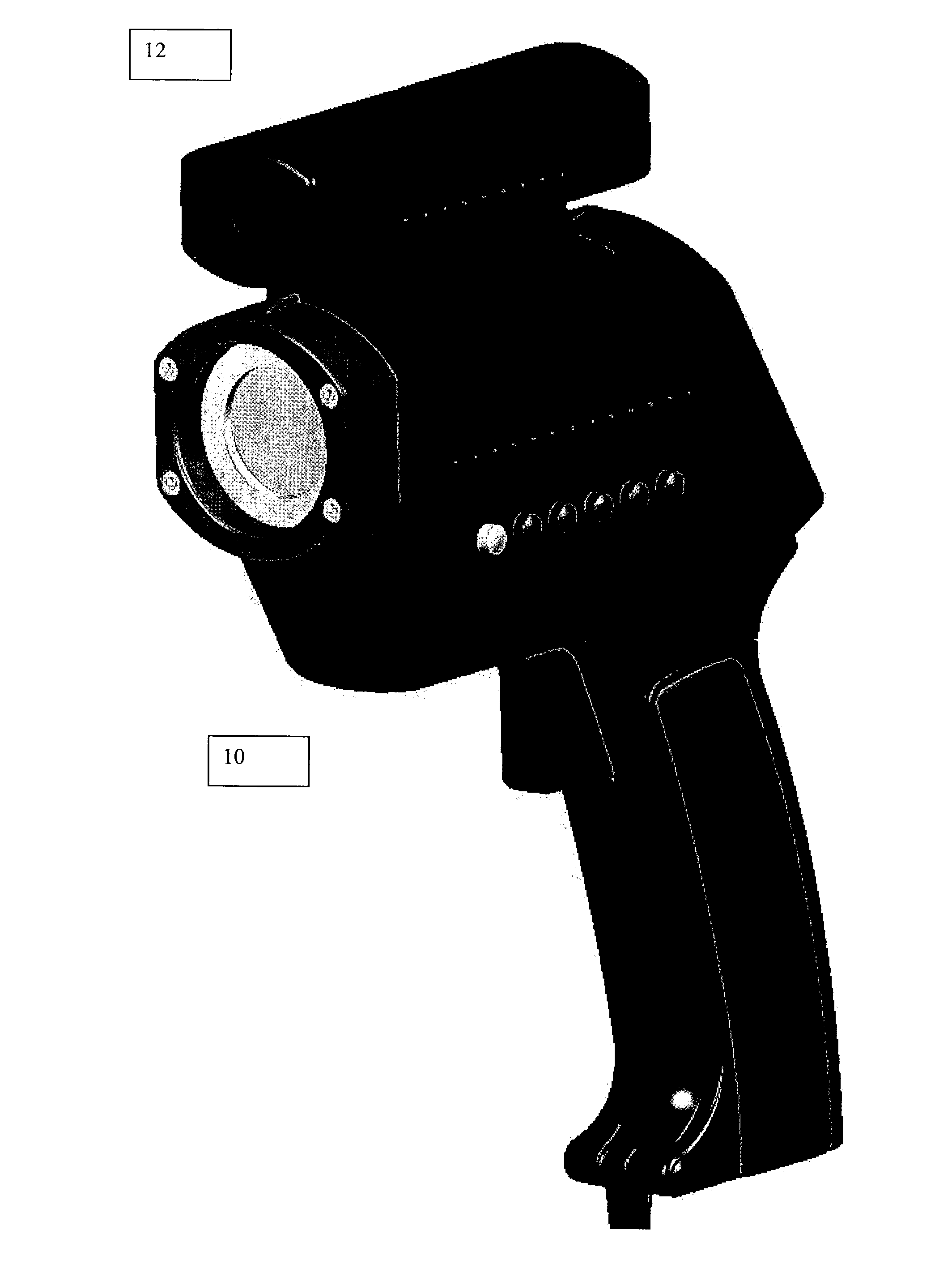
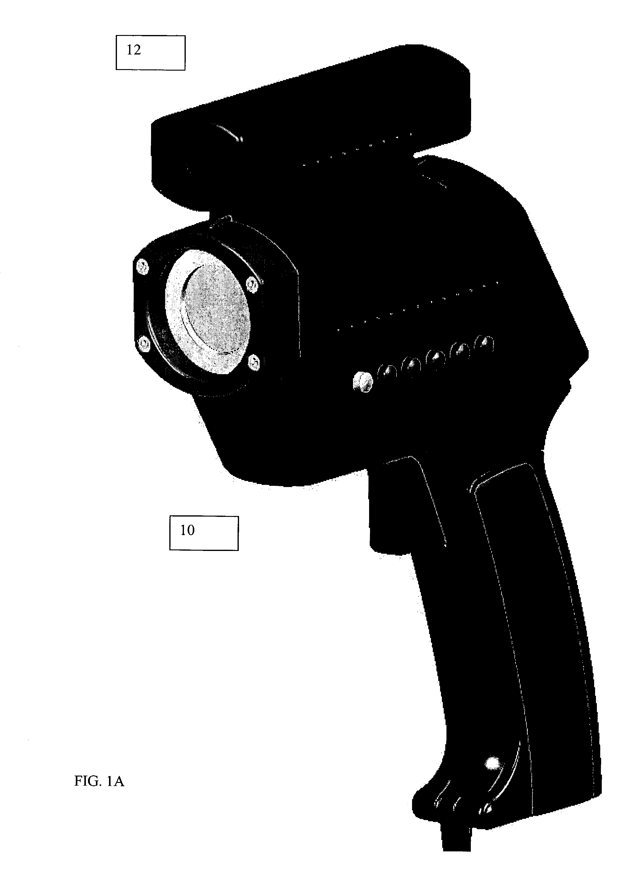
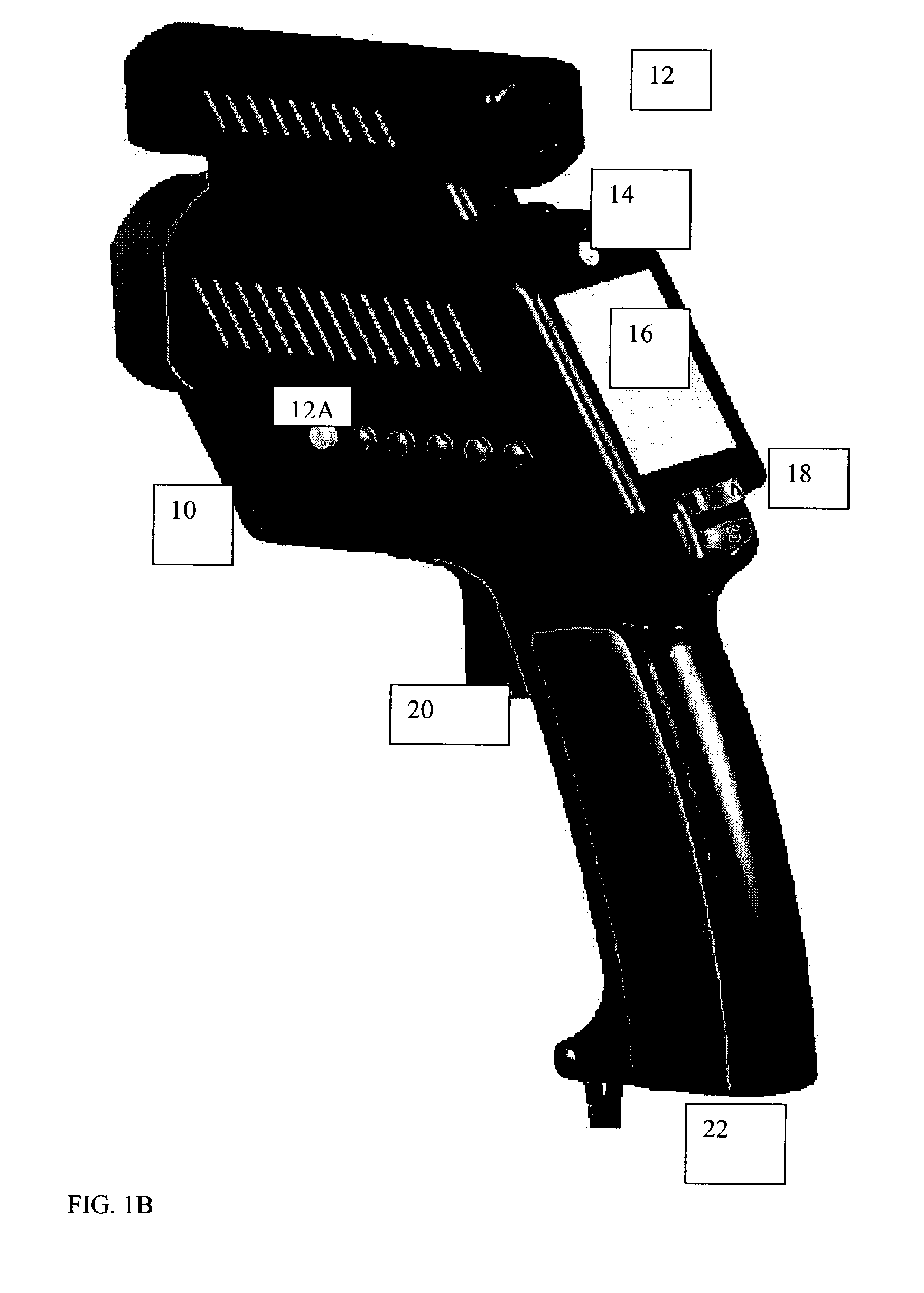
  • Radiometer with digital imaging system
  • Radiometer with digital imaging system
  • Radiometer with digital imaging system

Examples


Embodiment Construction

[0014]Reference will now be made in detail to various embodiments of the invention. Examples of these embodiments are illustrated in the accompanying drawings. While the invention will be described in conjunction with these embodiments, it will be understood that it is not intended to limit the invention to any embodiment. On the contrary, it is intended to cover alternatives, modifications, and equivalents as may be included within the spirit and scope of the invention as defined by the appended claims. In the following description, numerous specific details are set forth in order to provide a thorough understanding of the various embodiments. However, the present invention may be practiced without some or all of these specific details. In other instances, well known process operations have not been described in detail in order not to unnecessarily obscure the present invention.

[0015]In a preferred embodiment of the invention, a digital photography capability is added to a radiomet...


PUM


Abstract

A radiometer includes an integrally mounted digital camera aligned to image the energy zone of the radiometer. When digital photographs are taken they are time stamped and stored in memory. The images may be viewed on a viewer integrated into the radiometer digital camera system or downloaded to a computer for formatting or viewing.

Description

BACKGROUND OF THE INVENTION[0001]This application claims priority from provisional Patent Application No. 60 / 364,993 filed Mar. 13, 2002 entitled radiometer WITH DIGITAL IMAGING SYSTEM and Provisional Patent Application No. 60 / 392,733 filed Jun. 27, 2002 entitled radiometer WITH DIGITAL IMAGING SYSTEM both of which are hereby incorporated by reference for all purposes.[0002]Radiometers, or infrared thermometers, are used to remotely measure temperatures. The radiometer includes an infrared sensor and infrared optics to form an image of a portion of a remote object, the energy zone, on the sensor. The radiometer calculates the temperature of the imaged energy zone based on the intensity of the infrared radiation focused on the infrared detector.[0003]Various techniques exist to align the radiometer to measure a particular portion, the energy zone, of an object. Some existing techniques include optical alignment systems such as a telescope and laser alignment systems that project a sp...

Claims


Application Information

Patent Timeline
IPC IPC(8): G01J5/00H04N5/225H04N5/232H04N5/33
CPCG01J5/02G01J5/025G01J5/0265G01J5/08H04N5/332H04N5/2252H04N5/23293H04N5/33G01J5/0859G01J2005/0077H04N23/51H04N23/50H04N23/63H04N23/20H04N23/11G01J5/03
Inventor KIENITZ, ULRICH
Owner RAYTEK
Learn More