Cutting tool

a cutting tool and tool head technology, applied in the field of cutting tools, can solve the problems of awkward or impossible access to the clamping screw, screw head placement, and large clamping mechanism

Active Publication Date: 2006-08-22
ISCAR LTD
View PDF7 Cites 35 Cited by
  • Summary
  • Abstract
  • Description
  • Claims
  • Application Information

AI Technical Summary

Benefits of technology

[0010]Preferably in accordance with the first embodiment of the present invention, the pocket through bore is provided with an obstacle preventing the complete withdrawal of the fastener from the pocket through bore.
[0011]Further preferably in accordance with the first embodiment of the present invention, the intermediate cylindrical portion is provided with a longitudinally extending recess having forward and rear ends, the recess being bound by

Problems solved by technology

Often with such cutting tools handling difficulties are encountered when removing or replacing the cutting insert, seeing that this requires loosening, removal and screw insertion of the clamping screw in environments in which approach to the clamping screw is either awkward or impossible.
Clamps form part of a clamping mechanism that is rather bulky and are not suitable for shanks of very smal

Method used


Image

  • Cutting tool
  • Cutting tool
  • Cutting tool

Examples


Embodiment Construction

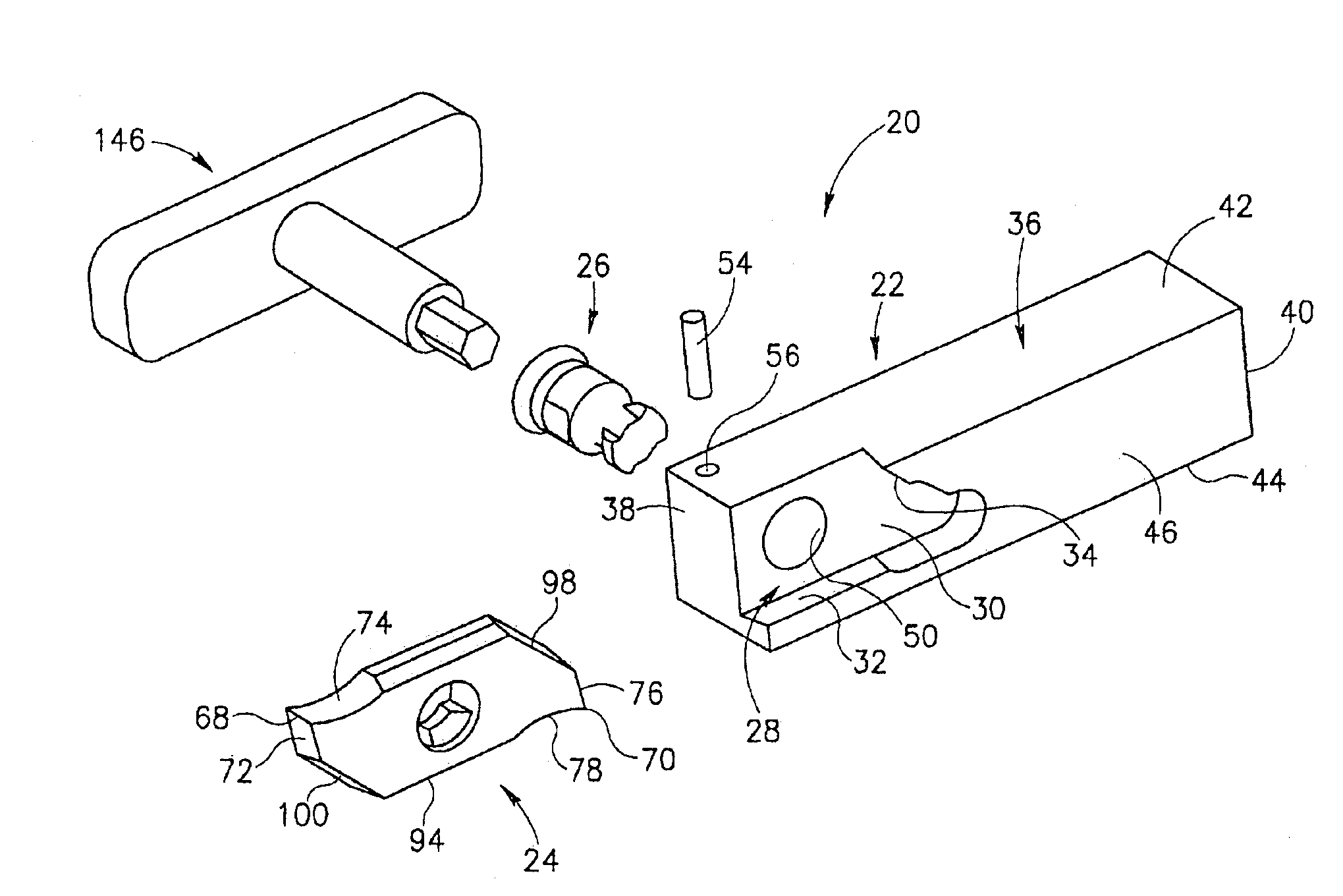
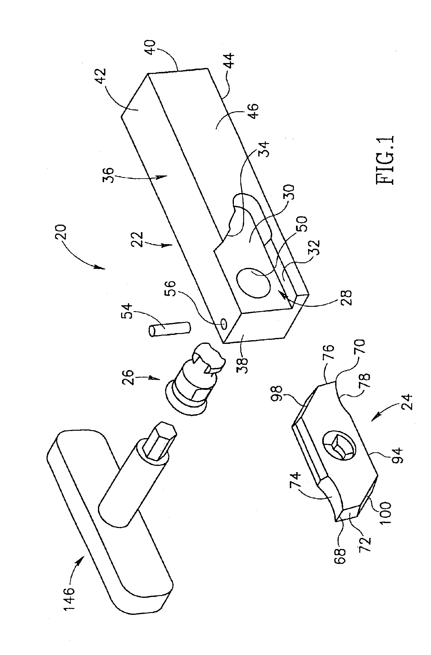
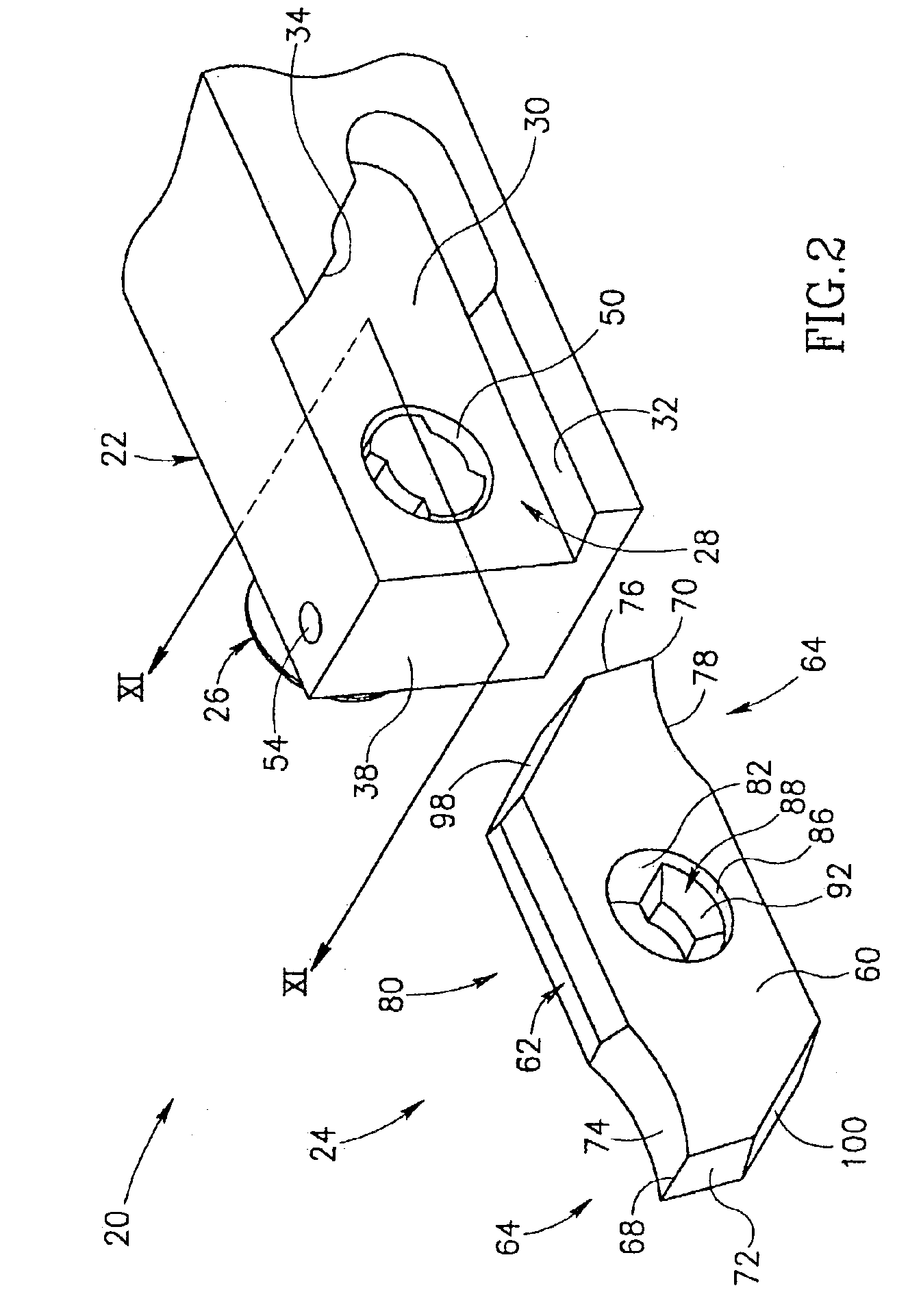
[0039]In the following description, the invention is illustrated for a cutting tool of the type typically used for a Swiss-type automatic lathe. However, the invention is directed to the secure retaining of a cutting insert in an insert pocket of a cutting tool. More precisely, the invention is directed to a coupling arrangement between a fastener and a cutting insert and therefore it will be appreciated that the invention is in no way whatsoever restricted to the cutting tools of the type used for Swiss-type automatic lathes, but is applicable to many types of cutting tools wherein a cutting insert is to be secured to an insert pocket by means of a fastener.

[0040]Attention is first drawn to FIGS. 1 to 3, showing a cutting tool in accordance with a first embodiment of the present invention. The cutting tool 20 comprises a tool body 22 and a cutting insert 24 secured by a fastener 26 in an insert pocket 28 of the tool body 22. The insert pocket 28 comprises a base wall 30 and first a...


PUM

PropertyMeasurementUnit
Diameteraaaaaaaaaa
Shapeaaaaaaaaaa

Abstract

A cutting tool has a tool body in which a cutting insert is secured to an insert pocket in the tool body by a fastener. In contrast to the use of a threaded clamping screw, the fastener remains in engagement with the tool body during all stages of the attachment and clamping, or unclamping and removal of the cutting insert. The fastener is rotatable between a clamping position and a non-clamping position by means of one of two keys. One key being capable of engaging one of the fastener's ends, and the other key being capable of engaging the other of the fastener's ends. This is particularly convenient for circumstances where the approach to one or the other of the fastener's ends may be obstructed.

Description

FIELD OF THE INVENTION[0001]This invention relates to a cutting tool of the kind having a replaceable cutting insert.BACKGROUND OF THE INVENTION[0002]Such cutting tools are well known particularly where the cutting insert is replaceably retained by a clamping screw in an insert pocket of the cutting tool. Often with such cutting tools handling difficulties are encountered when removing or replacing the cutting insert, seeing that this requires loosening, removal and screw insertion of the clamping screw in environments in which approach to the clamping screw is either awkward or impossible. For example, in Swiss-type automatic machines cutting tools have tool shanks that are typically made of rectangular shaped bars having a cross-sectional width of between 7 and 12 mm. The cutting insert is clamped in the insert pocket either by means of a screw or a clamp. Screw clamping is disclosed in U.S. Pat. No. 5,779,400 and DE 3114460 A1. Clamps form part of a clamping mechanism that is rat...

Claims


Application Information

Patent Timeline
IPC IPC(8): B23P15/28B23B27/16B23B27/08
CPCB23B27/08B23B2200/3618B23B2240/04Y10T407/2282Y10T407/228Y10T407/2272Y10T407/2274B23B2260/078B23B27/16
Inventor HECHT
Owner ISCAR LTD
Why Eureka
Try Eureka