Vertical shaft driving device for vertical wind mills or the like and electric power generator using the same

a technology of vertical shaft windmills and driving devices, which is applied in the direction of rotating machines/engines, renewable energy generation, machines/engines, etc., can solve the problems of large torque of drag-based vertical shaft windmills, low rotational speeds and energy conversion efficiency thereof, and hindered rotation of windmills. achieve the effect of reducing the drag force working to the blades, reducing the drag force, and increasing the wind speed

Inactive Publication Date: 2006-08-22
LEDERER YURIKO +1
View PDF10 Cites 31 Cited by
  • Summary
  • Abstract
  • Description
  • Claims
  • Application Information

AI Technical Summary

Benefits of technology

[0014]Namely, in the vertical shaft driving device, a plurality of rotary blades each including a blade supported on a planetary shaft are equally arranged circumferentially of a central shaft and capable of orbital motion integrally with the central shaft, and the rotary blades are arranged in a multipoint intersection form, in which blade faces of the blades are obliquely disposed with respect to radial directions with a center at the central shaft. By arranging the blades in the multipoint intersection form, it is possible to provide the vertical shaft driving device, in which air flows or water flows can be efficiently utilized to obtain a great output power.
[0058]The blade angle β is usually designed at 30–45 degrees, but the rotation control unit makes the blade angle β larger when the wind speed exceeds a predetermined speed. In FIG. 15, the blade angles β are 90 degrees. In the wind mill having the rotation control unit, the blade angles β are made larger with increasing the wind speed, finally the blades are arranged as shown in FIG. 15. By making the blade angles larger, the drag forces working to the blades are reduced, so that the rotational speed of the rotary blades can be maintained even if the wind speed increases. By employing the rotation control unit, damages of the wind mill, which are caused by strong winds, can be prevented.

Problems solved by technology

Torque of the drag-based vertical shaft wind mills are large, but rotational speeds and energy converting efficiency thereof are low, so the vertical shaft wind mills are not practically used, other than Savonius type wind mills, as electric generators.
However, in the Savonius type wind mill disclosed in Japanese Patent Gazette No. 11-62813 which has the fixed vanes provided on the outer side of the rotary blades, a part of air flows introduced by the fixed vanes collide with rear faces of the rotary blades (faces on the forward sides of the rotary blades), so that the rotation of the wind mill is hindered.
Namely, in the Savonius type wind mills, it is impossible to efficiently convert air flows, which have been intercepted, collected and straightened by the fixed vanes, into torque, so that it is difficult to highly increase the output power.
Water wheels are also required to efficiently use water flows, so water wheels driven by ocean streams, tides, etc. have the same disadvantages as the wind mills have.

Method used


Image

  • Vertical shaft driving device for vertical wind mills or the like and electric power generator using the same
  • Vertical shaft driving device for vertical wind mills or the like and electric power generator using the same
  • Vertical shaft driving device for vertical wind mills or the like and electric power generator using the same

Examples


Embodiment Construction

[0074]Preferred embodiments of the present invention, in which the vertical shaft driving device is applied to vertical shaft wind mills, will now be described in detail with reference to the accompanying drawings.

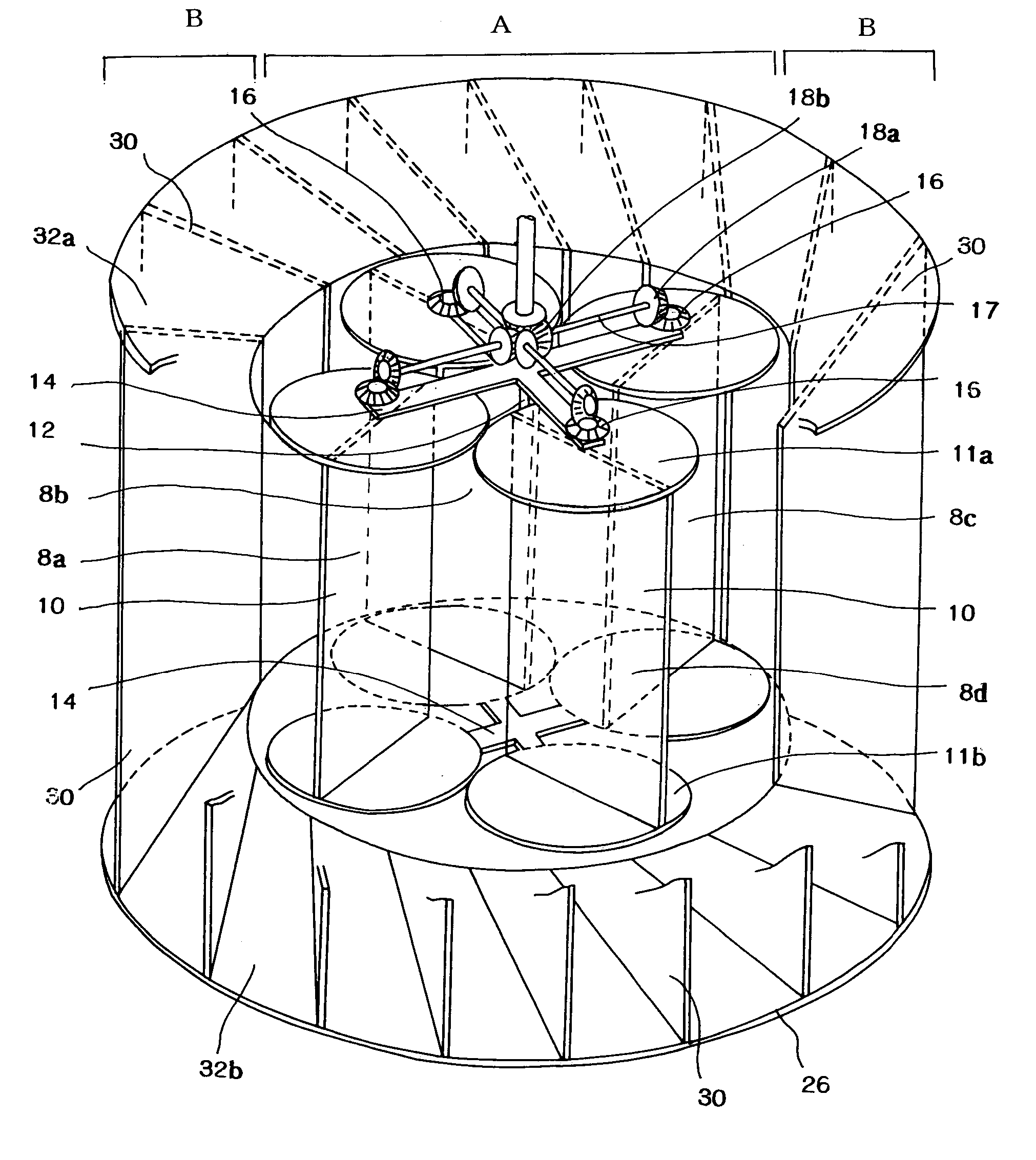
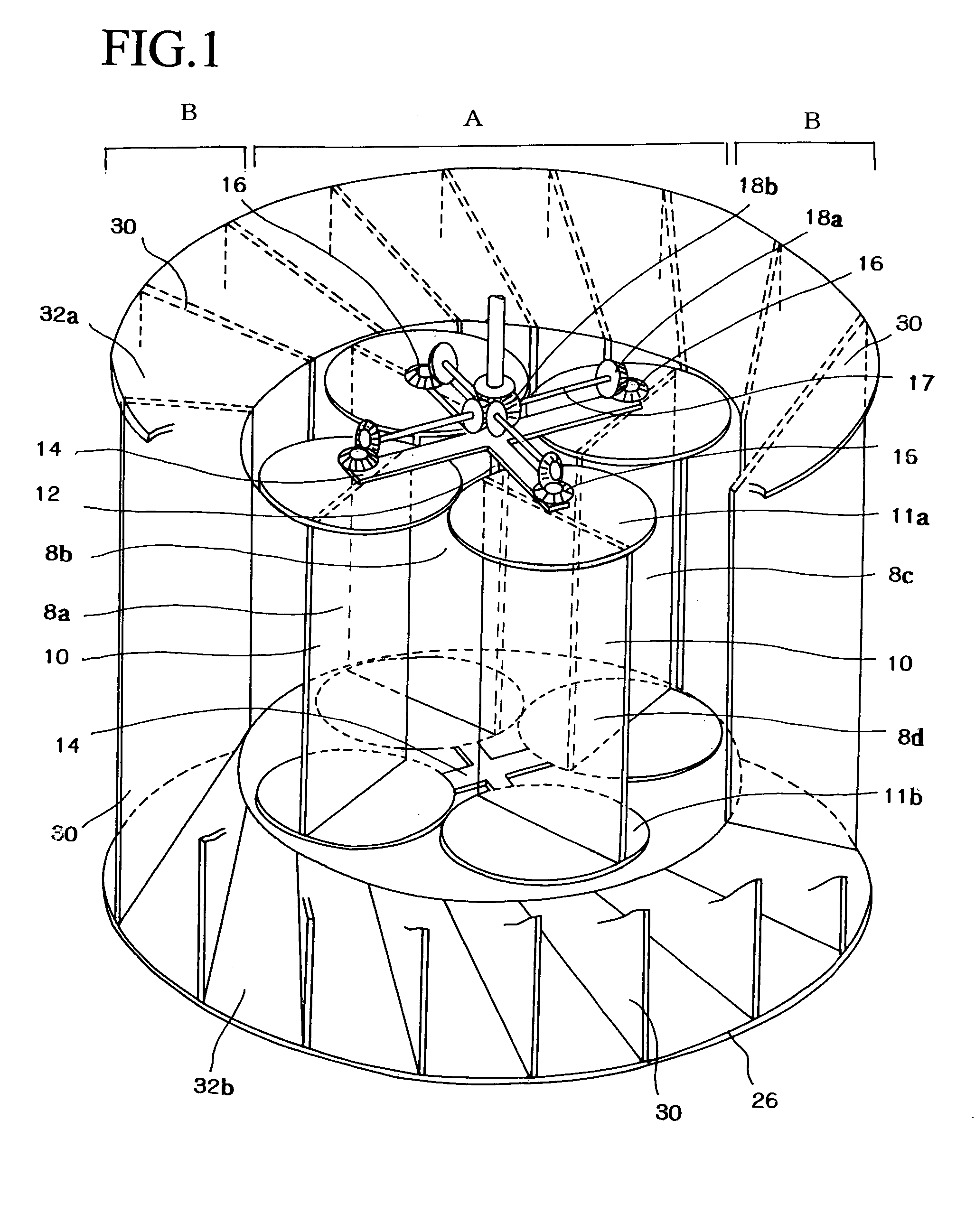
[0075]FIG. 1 is a perspective view of an embodiment of the vertical shaft wind mill relating to the present invention, and FIG. 2 is a front view of the vertical shaft wind mill. The vertical shaft wind mill of the present embodiment has: a cylinder section A, in which rotary blades are capable of moving along a circular orbit; a fixed vane section B circumferentially provided around the cylinder section A; a rotation control unit C for controlling a rotational speed of the rotary blades; and an electric generator D.

[0076]As shown in FIG. 1, the vertical shaft wind mill of the present embodiment has the four rotary blades 8a, 8b, 8c and 8d, which are provided in the cylinder section A, and arms 14, which are fixed to a central shaft 12, rotatably hold the rotary blades 8a,...


PUM


Abstract

A vertical shaft driving device wherein a plurality of rotary blades (8a, 8b, 8c and 8d) each including a blade (10) supported on a planetary shaft are equally arranged circumferentially of a central shaft (12) and capable of orbital motion integrally with the central shaft (12), and wherein the rotary blades are arranged in a multipoint intersection form, in which blade faces of the blades (10) are obliquely disposed with respect to radial directions with a center at the central shaft (12). By arranging the blades (10) in the multipoint intersection form, it is possible to provide the vertical shaft driving device, in which air flows or water flows can be efficiently utilized to obtain a great output power.

Description

FIELD OF TECHNOLOGY[0001]The present invention relates to a vertical shaft driving device, which is rotated by an air flow or a water flow, and an electric generator driven by the driving device.BACKGROUND OF TECHNOLOGY[0002]These days, importance of global environmental has increased, so a wind power attracts scientists' attention as clean energy, and many types of wind mills have been studied and developed. A drag-based vertical shaft wind mill is capable of operating without wind direction control, and aerodynamic noise, bad influence to scenery and moving shadows are less than those of a horizontal shaft wind mill, e.g., a propeller type wind mill, so the vertical shaft wind mills are good to install on roofs of houses and buildings as small-scale electric generators. Torque of the drag-based vertical shaft wind mills are large, but rotational speeds and energy converting efficiency thereof are low, so the vertical shaft wind mills are not practically used, other than Savonius t...

Claims


Application Information

Patent Timeline
Patent Type & Authority Patents(United States)
IPC IPC(8): F03B15/06F03D7/06F03B17/06F03D3/02F03D3/04F03D3/06
CPCF03B17/067F03D3/02F03D3/0418F03D3/068Y10S415/907F05B2260/5032Y02E10/28Y02E10/74F03D15/10F03D3/0409F03D9/25Y02E10/30Y02E10/20
Inventor KURITA, HIDEMI
Owner LEDERER YURIKO
Why Eureka
Try Eureka