
Single wire bus communication system with method for handling simultaneous responses from multiple clients

a communication system and single wire technology, applied in logic circuits, instruments, reliability increasing modifications, etc., can solve problems such as the upper limit of the ratio of pull-ups to pull-downs, and the number of client devices

Active Publication Date: 2006-08-22
ANALOG DEVICES INC
View PDF12 Cites 20 Cited by
  • Summary
  • Abstract
  • Description
  • Claims
  • Application Information

AI Technical Summary

Benefits of technology

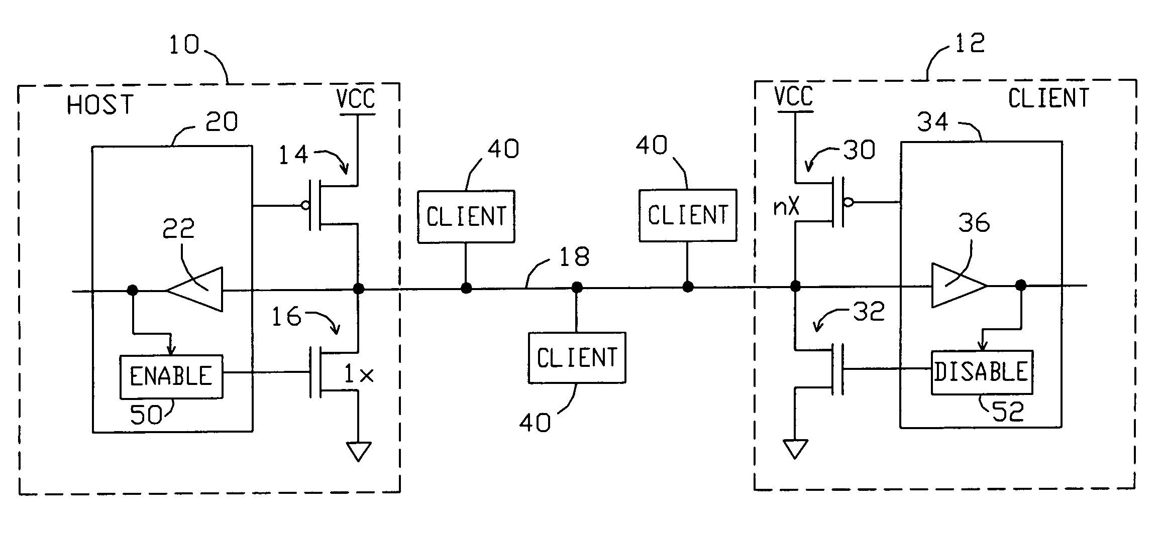
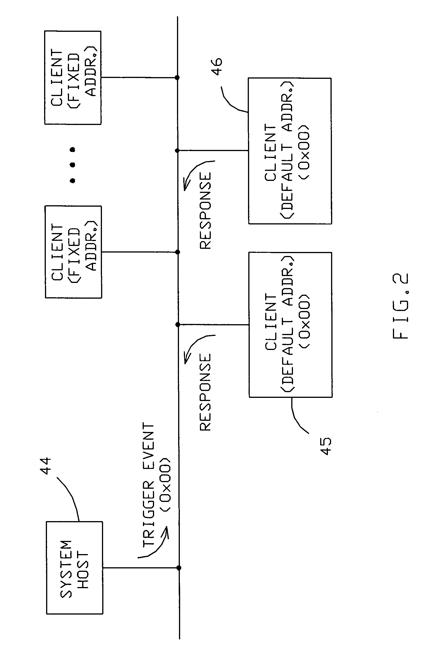
The present invention is a single wire bus communication system that allows multiple devices to respond to a command that requires a response from multiple clients. The system includes a host device and at least one client device, each with a pull-up and a pull-down device. In response to a trigger event that requires responses from multiple client devices simultaneously, the host device enables its pull-down transistor and disables its pull-up transistor, while each client device's pull-up transistor conducts more current than the host device's pull-down transistor. This allows one or more of the client devices' strong pull-ups to override the single weak pull-down on the bus, increasing the number of client devices that can respond to the command. The invention also contemplates opposite polarity implementations.

Problems solved by technology

This can result in some devices trying to pull the bus wire up, and other devices trying to pull it down.
However, this approach imposes an upper limit on the ratio of pull-ups to pull-downs, and thus on the number of client devices that may respond to a command that requires a response from multiple clients.

Method used


Image

  • Single wire bus communication system with method for handling simultaneous responses from multiple clients
  • Single wire bus communication system with method for handling simultaneous responses from multiple clients
  • Single wire bus communication system with method for handling simultaneous responses from multiple clients

Examples


Embodiment Construction

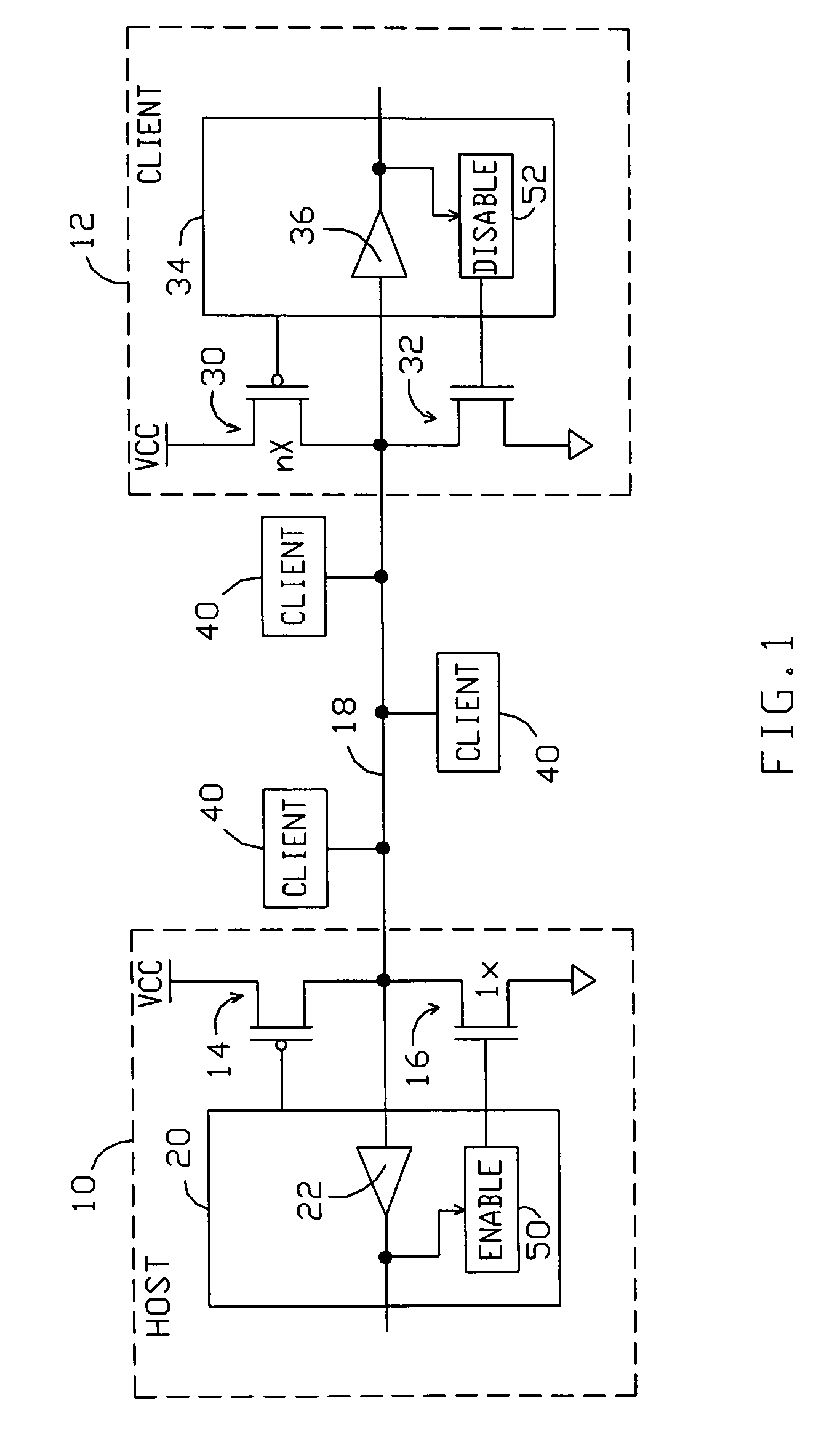
[0016]A schematic diagram of the physical layer of a single-wire bus communication system per the present invention is shown in FIG. 1. The system comprises an originating device 10 capable of initiating communications on the bus, typically a “host” device, and at least one client device 12. Host device 10 includes two bus drive devices: a pull-up device 14 and a pull-down device 16, each of which is connected to the system's bus wire 18. Host device 10 also includes control circuitry 20, which comprises a receiver 22 and control logic (not shown) which operates the pull-up and pull-down devices. When pull-up device 14 is “enabled” by control circuitry 20, it is turned on and conducts current to bus wire 18 to pull it up to a logic “high” level. Similarly, when pull-down device 16 is enabled, it conducts current to pull bus wire 18 down to a logic “low” level.

[0017]Client device 12 includes similar components: a pull-up device 30 and a pull-down device 32, each of which is connected...


PUM


Abstract

A single wire bus communication system comprises a bus wire, a host device, and at least one client device, with each host and client device having pull-up and pull-down transistors to pull the bus wire “high” or “low”, respectively. The system is arranged such that, in response to a “trigger event” that requires responses from multiple client devices simultaneously, the host device enables its pull-down transistor, and each client device disables its pull-down transistor when conveying a “low” logic level onto the bus. To avoid bus contention, each client's pull-up transistor is arranged to conduct more current when enabled than the host's pull-down transistor. Then, one or more of the client devices' strong pull-ups will overcome the single weak pull-down on the bus, thereby enabling numerous client devices to respond to a command that requires a response from multiple clients.

Description

BACKGROUND OF THE INVENTION[0001]1. Field of the Invention[0002]This invention relates to the field of single wire bus communication systems, and particularly to methods of handling simultaneous responses from multiple clients.[0003]2. Description of the Related Art[0004]Single wire bus communication systems which convey digital data between host and client devices connected to the bus wire are well-known. For example, the system described in U.S. Pat. No. 6,532,506 to Dunstan and Stolizka, and the “1-Wire® bus” are single wire systems found in computer and communication systems. Also common are two wire system management busses utilizing two wires where the data signal is synchronized by a clock signal. For example, the SMBus and the I2C bus systems are two-wire busses found in computer systems.[0005]Such busses typically comprise at least one host device and a number of client devices, all connected to a common bus wire. At the system's physical layer, each host and client device ...

Claims


Application Information

Patent Timeline
Patent Type & Authority Patents(United States)
IPC IPC(8): H03K19/0175
CPCG06F13/4286G06F13/4077
Inventor STOLITZKA, DALE F.DUNSTAN, ROBERT A.
Owner ANALOG DEVICES INC
Learn More