Original scanning apparatus

a scanning apparatus and scanning technology, applied in the direction of electrical apparatus, instruments, computing, etc., can solve the problems of deteriorating reading accuracy, resin deformation, and inability to accurately reflect light from the mirror on the reading sensor, so as to achieve stable scanning of the original

Inactive Publication Date: 2006-08-22
CANON KK
View PDF10 Cites 7 Cited by
  • Summary
  • Abstract
  • Description
  • Claims
  • Application Information

AI Technical Summary

Benefits of technology

[0012]The present invention has been devised in view of the above and other drawbacks, and it is an object of the present invention to provide an original scanning apparatus for constantly maintaining a posture of a reflecting member even with the influence of heat and performing stable scanning of an original.

Problems solved by technology

Thus, when reading of images is continued for a long time, temperature of the carriage rises to cause deformation of resin.
Then, when the resin material is deformed by expansion or the like due to thermal deformation, supporting portions of reflecting mirrors move and deform, whereby positions and angles of the mirrors change to cause such a problem in that reflected light from the mirrors is not incident on a reading sensor accurately.
In particular, in an image reading apparatus according to an image flow reading system which is provided with an automatic feeding mechanism of an original and reads an image by moving an original in a state in which an optical system is fixed, since the optical system is continuously in a reading state while a plurality of originals set in the automatic feeding mechanism are read, deterioration of reading accuracy due to the rise of temperature is a critical problem.

Method used


Image

  • Original scanning apparatus
  • Original scanning apparatus
  • Original scanning apparatus

Examples


first embodiment

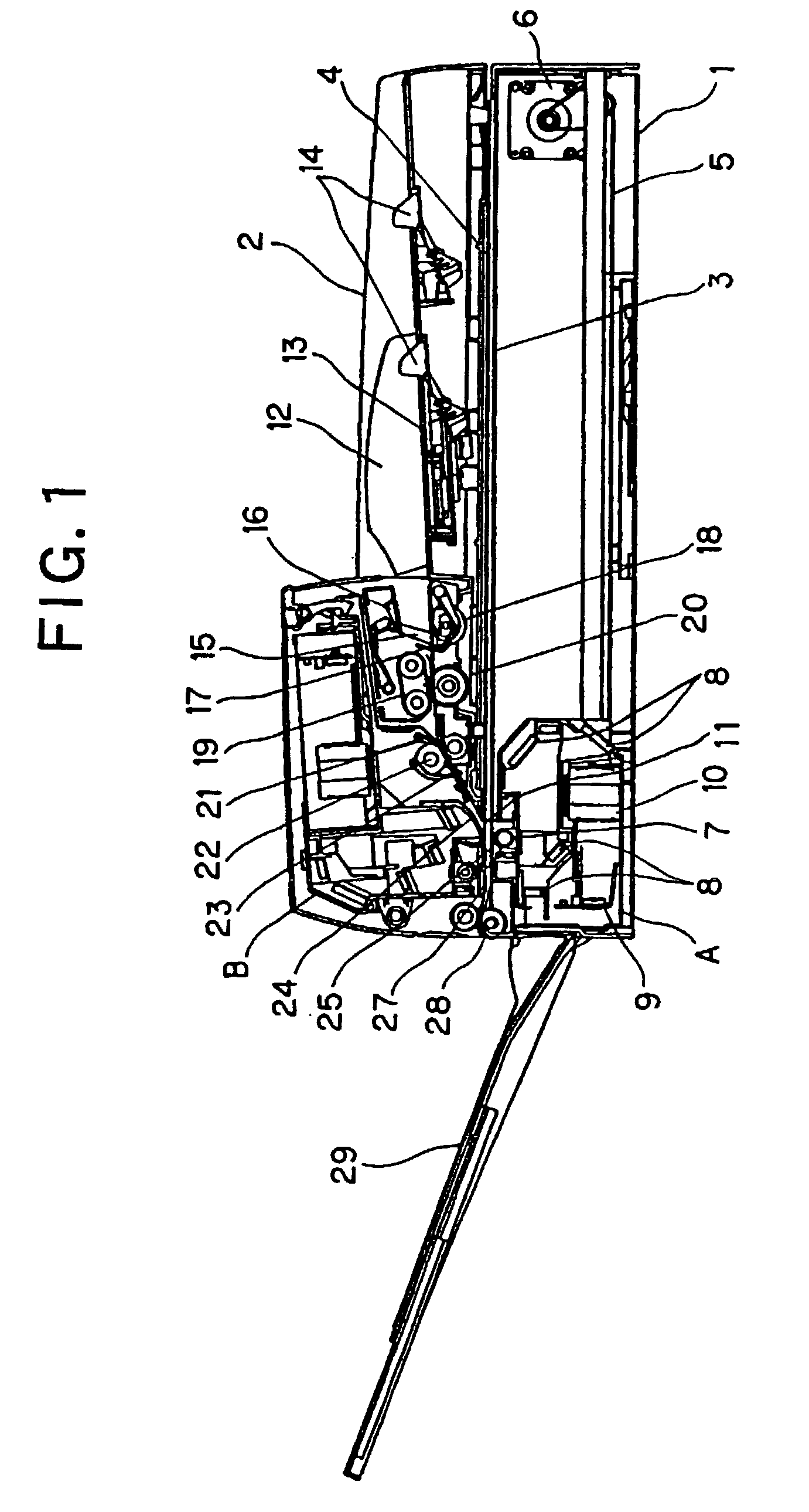
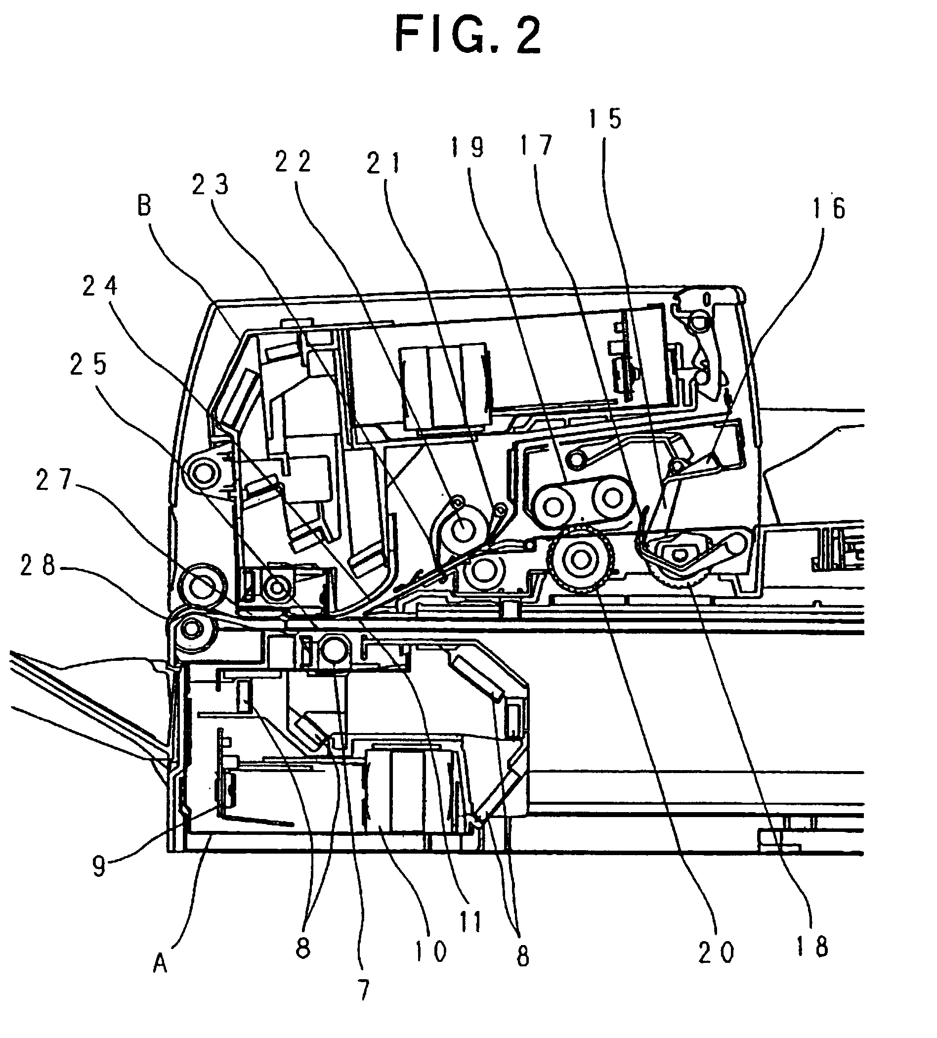
[0025]A first embodiment of the present invention will be described with reference to FIGS. 1 to 5. FIG. 1 is a side sectional view schematically showing a structure of an image reading mechanism (image reading apparatus) functioning as an original scanning apparatus in accordance with the first embodiment of the present invention. In addition, FIG. 2 is an enlarged side sectional view showing an original conveying unit of the mechanism.

[0026]As shown in FIGS. 1 and 2, the image reading apparatus is constituted of a flat bed (FB) image reading unit (FB unit) 1 for mounting and fixing an original and reading its surface image and an automatic sheet-feeding device (ADF unit) 2 attached to an upper surface of the FB unit 1. Moreover, a part of the FB unit 1 and a part of the ADF unit 2 are combined to form an image flow reading unit.

[0027]The FB unit 1 is a mechanism for scanning and reading a surface image of an original mounted and fixed thereon. The FB unit 1 is provided with a refe...

second embodiment

(Second Embodiment)

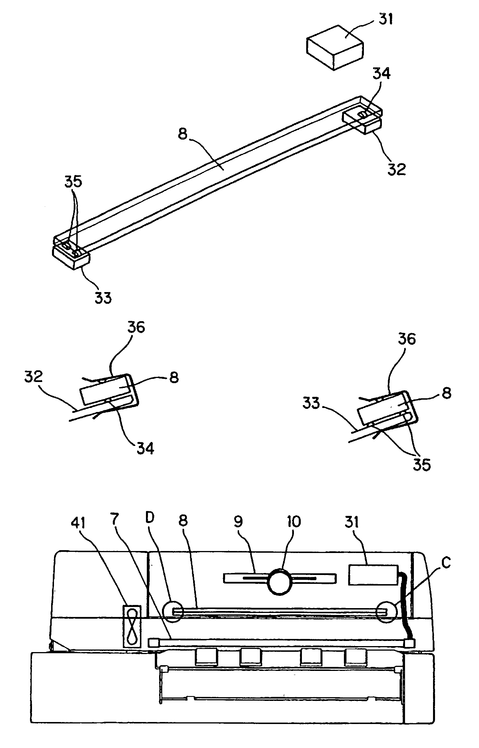
[0062]FIG. 6 shows a second embodiment of the present invention. FIG. 6 is a schematic view of the second optical carriage B in accordance with the second embodiment of the present invention which is viewed from the discharge stacking tray 29 side.

[0063]In this embodiment, in addition to the configuration of the first embodiment, a fan 41 functioning as cooling means is provided in an image reading apparatus to cool the second optical carriage B in order to suppress the rise of temperature in the second optical carriage B. In this case, in the mirror supporting portion inside the second optical carriage B, an end on a D side close to the fan 41 is supported at two points and an end on a C side distant from the fan 41 is supported at one point. That is, the fan 41 is provided on a second end side of a reflecting mirror.

[0064]The second optical carriage B is cooled more on the side close to the fan 41, which means that the end on the D side close to the fan 41 is co...


PUM


Abstract

Deformation of a second optical carriage (B) due to heat is large on a (C) side where an inverter (31) is attached and small on a (D) side. A mirror supporting portion inside the second optical carriage (B) supports the mirror at one point on the (C) side and at two points on the (D) side. An angle of the reflecting mirror (8) depends on two protrusions on the (D) side where thermal deformation is small, and the mirror is supported at one point on the (C) side where thermal deformation is large. Thus, even if an angle of the mirror supporting portion (C) changes, the angle of the reflecting mirror (8) is not affected. Therefore, a change in the angle of the reflecting mirror (8) can be controlled to be small when temperature of the second optical carriage (B) rises during a reading operation, and decrease in reading accuracy due to thermal deformation of the second optical carriage (B) can be suppressed.

Description

BACKGROUND OF THE INVENTION[0001]1. Field of the Invention[0002]The present invention relates to an original scanning apparatus for scanning an original, and particularly, to an apparatus having a reflecting member for reflecting light from an original.[0003]2. Description of the Related Art[0004]A reading optical system in an image reading apparatus functioning as an original scanning apparatus is constituted of a light source, a reflecting mirror, a lens, a reading sensor and the like.[0005]Conventional image reading apparatuses include the following two types. One is an image reading apparatus with an optical system of an integral optical carriage system that has all elements of the optical system in one optical carriage. The other is an image reading apparatus with an optical system of a mirror movement system in which a lens and a reading sensor are fixed to a main body of the image reading apparatus and a first optical carriage having a light source and a mirror and a second o...

Claims


Application Information

Patent Timeline
Patent Type & Authority Patents(United States)
IPC IPC(8): H04N1/04H04N1/40G06T1/00H04N1/028H04N1/031H04N1/10
CPCH04N1/00986H04N1/031H04N2201/02497H04N2201/0246H04N2201/02472H04N1/1013
Inventor OGATA, ATSUSHI
Owner CANON KK
Why Eureka
Try Eureka