Optical distance compensation device and method of scanning plane laser

A technology of scanning plane and compensation device, applied in the field of optical detection, can solve the problems of large measurement accuracy and correction effect, non-parallel between light sources, etc., achieves simple and stable structure, concise design, and is conducive to calibration and correction and three-dimensional reconstruction. Effect

Inactive Publication Date: 2016-03-30
INST OF MICROELECTRONICS CHINESE ACAD OF SCI
View PDF5 Cites 0 Cited by
  • Summary
  • Abstract
  • Description
  • Claims
  • Application Information

AI Technical Summary

Problems solved by technology

[0004] In the past, the sheet light source scanning solutions at home and abroad obtained the sheet light source through a cylindrical lens, and used a galvanometer, a rotating drum, and a rotary scanner to realize the sheet light source scanning. The sheet light sources are not parallel, which has a great impact on measurement accuracy and calibration.

Method used


Image

  • Optical distance compensation device and method of scanning plane laser
  • Optical distance compensation device and method of scanning plane laser
  • Optical distance compensation device and method of scanning plane laser

Examples


Embodiment Construction

[0031] In order to make the object, technical solution and advantages of the present invention clearer, the present invention will be described in further detail below in conjunction with specific embodiments and with reference to the accompanying drawings.

[0032] It should be noted that all expressions using "first" and "second" in the embodiments of the invention are used to distinguish two entities with the same name but different parameters or parameters that are not the same. It can be seen that "first" and "second" are only For the convenience of expression, it should not be understood as a limitation on the embodiments of the invention, and the following embodiments will not describe them one by one.

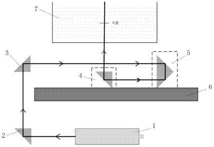
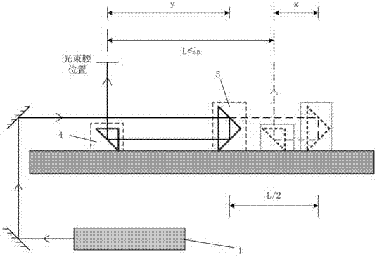
[0033] see figure 1 , which is a schematic diagram of the optical path refraction of the optical path compensation device for scanning a plane laser according to an embodiment of the present invention. As an embodiment of the present invention, the optical path compens...


PUM


Abstract

The invention discloses an optical distance compensation device and method of scanning plane laser. The optical distance compensation device comprises a scanning guide rail platform, a scanning reflection mechanism and a fold-back compensation mechanism, wherein the scanning reflection mechanism and the fold-back compensation mechanism can move on the scanning guide rail platform; the fold-back compensation mechanism is used for reflecting a laser sheet light source to the scanning reflection mechanism; the scanning reflection mechanism is used for reflecting the laser sheet light source to a three-dimensional scalar field; the compensation mechanism and the scanning mechanism are arranged on the scanning guide rail platform in parallel and are driven by two motors respectively to move synchronously; and the speed of the compensation mechanism is one half of that of the scanning mechanism. According to the optical distance compensation device of the scanning plane laser, provided by the invention, a light path fold-back manner is reasonably arranged so that the device is compact, and the scanning reflection mechanism and the fold-back compensation mechanism can be conveniently mounted; and a light waist of the laser sheet light source is kept at the middle position of a water tank through the arraying manner and synchronous movement relation of the scanning reflection mechanism and the fold-back compensation mechanism, and the thickness of sheet light in a scanning region of the water tank is smaller than required thickness.

Description

technical field [0001] The invention relates to the technical field of optical detection, in particular to a 3DLIF-based optical path compensation device for scanning plane laser and a method thereof. Background technique [0002] 3DLIF technology, that is, "three-dimensional laser-induced fluorescence technology", is based on PLIF technology, moving the laser sheet light source to scan the measurement space, synchronously controlling the sheet light source scanning, camera and laser operation, collecting multi-section two-dimensional information and position information, and then passing Calibration, correction and three-dimensional reconstruction technology to obtain three-dimensional concentration (temperature) field. 3DLIF technology can not only qualitatively reveal the internal structure of the flow, but also can quantitatively measure the concentration field, temperature field, pressure field and velocity field when combined with image processing technology. It has be...

Claims


Application Information

Patent Timeline
Patent Type & Authority Applications(China)
IPC IPC(8): G01C25/00
CPCG01C25/00
Inventor 劳达宝周维虎郝春艳崔成君王国名纪荣祎董登峰张滋黎袁江刘鑫王岩庆石俊凯范百兴
Owner INST OF MICROELECTRONICS CHINESE ACAD OF SCI
Why Eureka
Try Eureka