Rain head

a technology of rain head and spherical head, which is applied in the direction of gravity filter, artificial water canal, building components, etc., can solve the problems of reducing the quality of water by coliforms from animal matter and turbidity, reducing the efficiency of screening in known rain head, and extending the time between maintenance of rain head. , to achieve the effect of increasing the efficiency of rain head and prolonging the time between maintenan

a technology of rain head and spherical head, which is applied in the direction of gravity filter, artificial water canal, building components, etc., can solve the problems of reducing the quality of water by coliforms from animal matter and turbidity, reducing the efficiency of screening in known rain head, and extending the time between maintenance of rain head. , to achieve the effect of increasing the efficiency of rain head and prolonging the time between maintenan

US7096627B2Inactive Publication Date: 2006-08-29WADE RODNEY GEORGE

Image

  • Rain head
  • Rain head
  • Rain head

Examples


Embodiment Construction

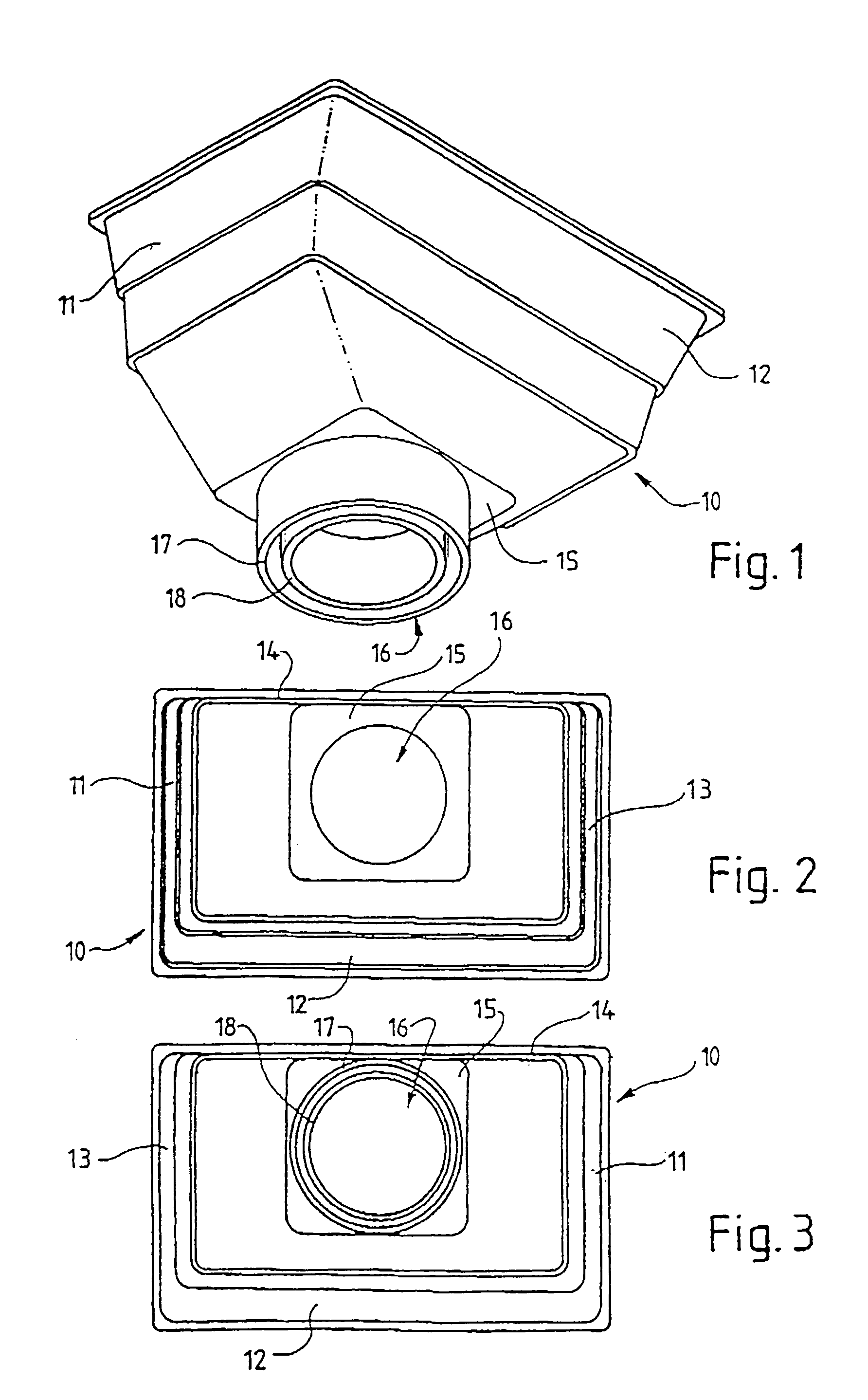
[0020]FIGS. 1 to 3 show a known rain head 10 having a substantially rectangular body with downwardly sploping walls 11, 12, 13 on three sides and a substantially perpendicular rear wall 14.

[0021]The base 15 of the rain head 10 is substantially horizontal and includes an outlet 16 formed centrally therewith. The outlet 16 is defined by two spigots 17, 18 each having a common central axis with the other. The spigots 17, 18 have a circular configuration for attachment to a downpipe by press fitting either with or without the use of an adhesive.

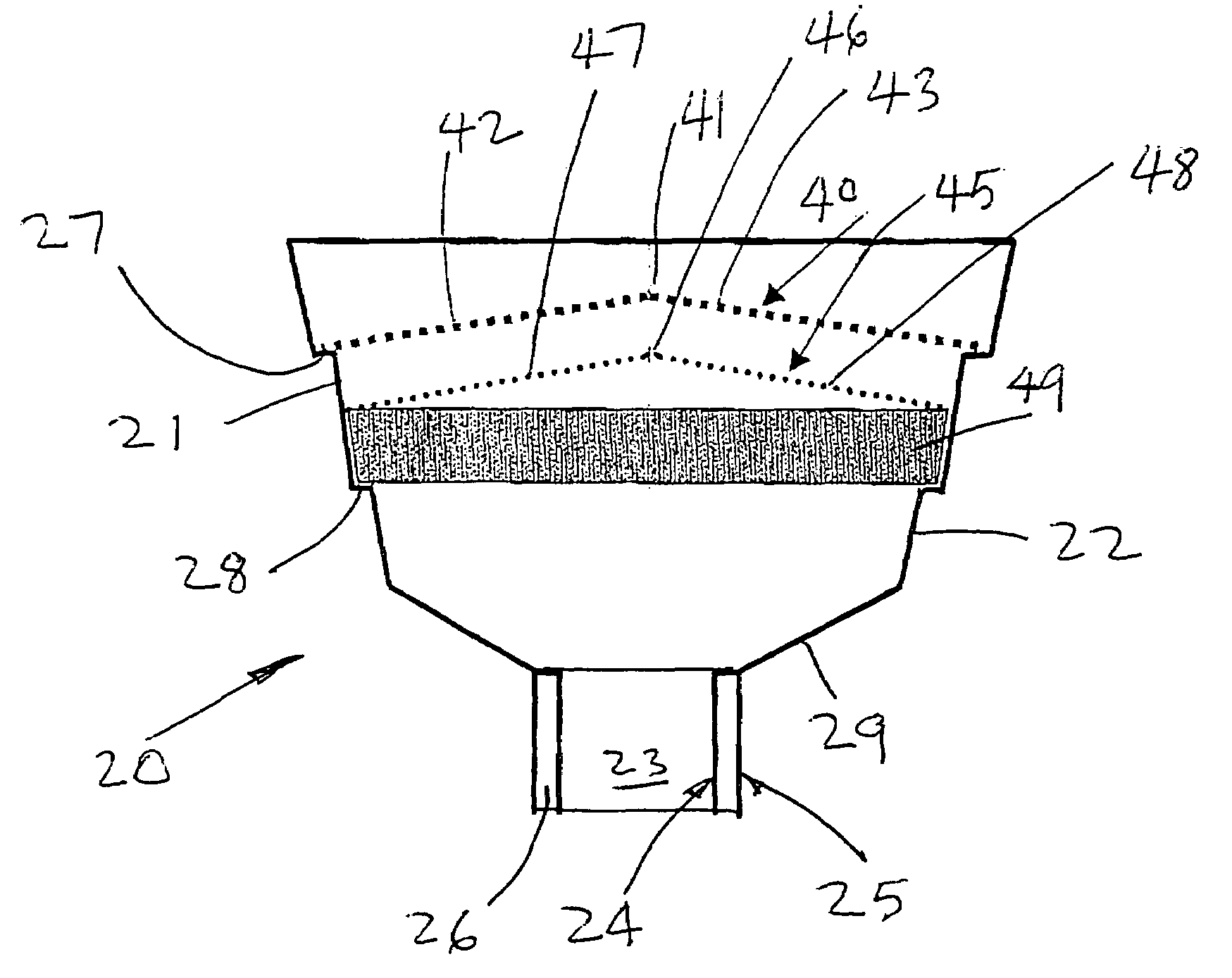
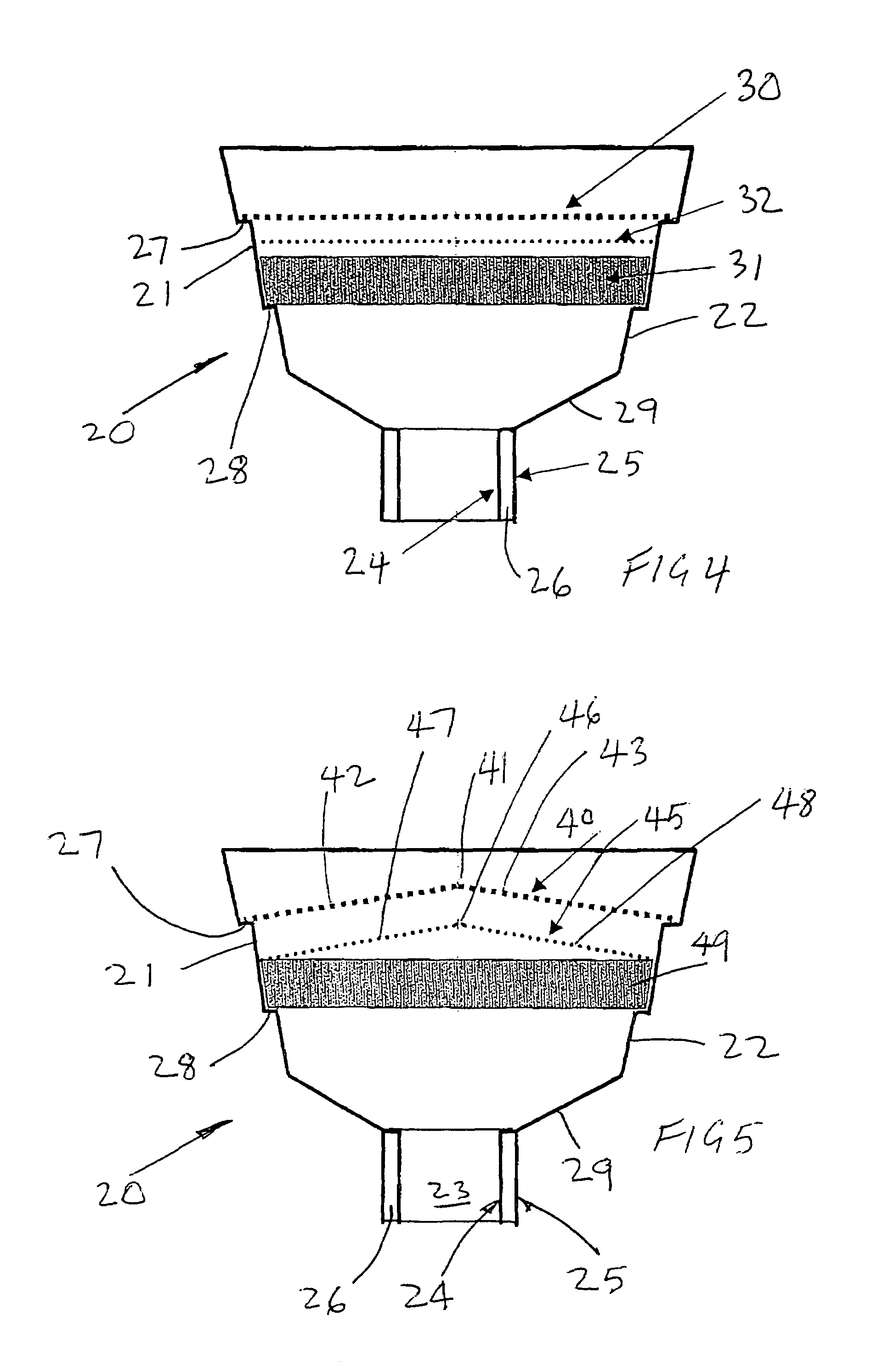
[0022]FIG. 4 shows a vertical sectional view through a rain head 20 according to one embodiment of the invention. The rain head 20 has downwardly sloping sides 21, 22. Three of the sides may slope downwardly as shown and the rear side may be substantially perpendicular like the prior rain head of FIGS. 1 to 3. The rain head 20 has an open top or inlet and an outlet 23 defined by spigots 24, 25. The spigots 24, 25 have a common central axis and a...


PUM

PropertyMeasurementUnit
aperture sizeaaaaaaaaaa
thicknessaaaaaaaaaa

Abstract

A rain head is disclosed having three filters through which water entering an inlet to the rain head must pass before passing out through an outlet from the rain head. The filters remove successively smaller particles from the water.

Description

BACKGROUND OF THE INVENTION[0001]This invention relates to a rain head. Rain heads are located adjacent the underside of a roof gutter and are attached to an upper end of a downpipe. Rain heads are designed to provide a “safety break” between the downpipe and the roof gutter. This safety break ensures that in the event of a downpipe blockage or rain head blockage from the gutter, water can escape and spill onto the ground and thus prevent flooding of the eaves, wall cavity and the building.[0002]When water from a roof of a building is captured for use and storage in a holding tank the quality of water is reduced by coliforms from animal matter and by turbidity.[0003]Coliforms are the result of animal matter entering the tank whilst turbidity is a result of suspended solids like fine dust particles and vegetable matter.[0004]In an attempt at reducing the presence of coliforms and reducing turbidity, known rain heads usually incorporate a single filter to exclude particles down to a s...

Claims


Application Information

Patent Timeline
29 Aug 2006
Publication
US7096627B2
IPC
E04D13/04; E04D13/064; E04D13/076; E04D13/08
CPC
E04D13/0645; E04D13/08; E04D13/0767; Y10T137/6969
Inventors
WADE, RODNEY GEORGE