Slip-preventing device for vehicle tire

a technology for vehicle tires and preventing devices, which is applied in the direction of non-skid devices, wheel attachments, transportation and packaging, etc., can solve the problems of taking a long time to fit the conventional tire chains on the tires, the work is complicated and troublesome for users, and the time required for attaching the tire chains is large for such users, so as to achieve the effect of short tim

Inactive Publication Date: 2006-08-29
SAKAKIBARA KOUICHI
View PDF24 Cites 7 Cited by
  • Summary
  • Abstract
  • Description
  • Claims
  • Application Information

AI Technical Summary

Benefits of technology

[0005]It is an object of the invention to provide a slip-preventing device for a tire that enables anyone to fit it on a tire in a short time.
[0007]The slip-preventing device of the tire may provide a free joint unit on the arm frame. In this case, the free joint unit defines a connecting portion and functions to move in the arm frame. Thus, the free joint unit releases a force applied to the arm frame or vibration at the time of rotating the tire or braking. Moreover, the free joint serves to facilitate installation to the tire.
[0008]The slip-preventing device of the tire may have an elastic body fitted on the free joint unit in the arm frame. In this case, the elastic body is composed of a spring, rubber or the like. When the elastic body is fitted on the free joint unit, it facilitates much more the installation to the tire and improves much more the absorption of the vibration or noise. Particularly, using them in combination improves much more the performance of the slip-preventing device.

Problems solved by technology

Generally, it is very laborious and takes much time to fit the conventional tire chains on the tires.
Such work is very complicated and troublesome for users who handle the tire chains once or twice a year.
Attaching the tire chains needs much time for such users.
Particularly, the fitting work becomes more difficult under bad condition such as the work on a snow-covered road.
Moreover, the attaching work is very hard for users who are weak such as women or the like.

Method used


Image

  • Slip-preventing device for vehicle tire
  • Slip-preventing device for vehicle tire
  • Slip-preventing device for vehicle tire

Examples


first embodiment

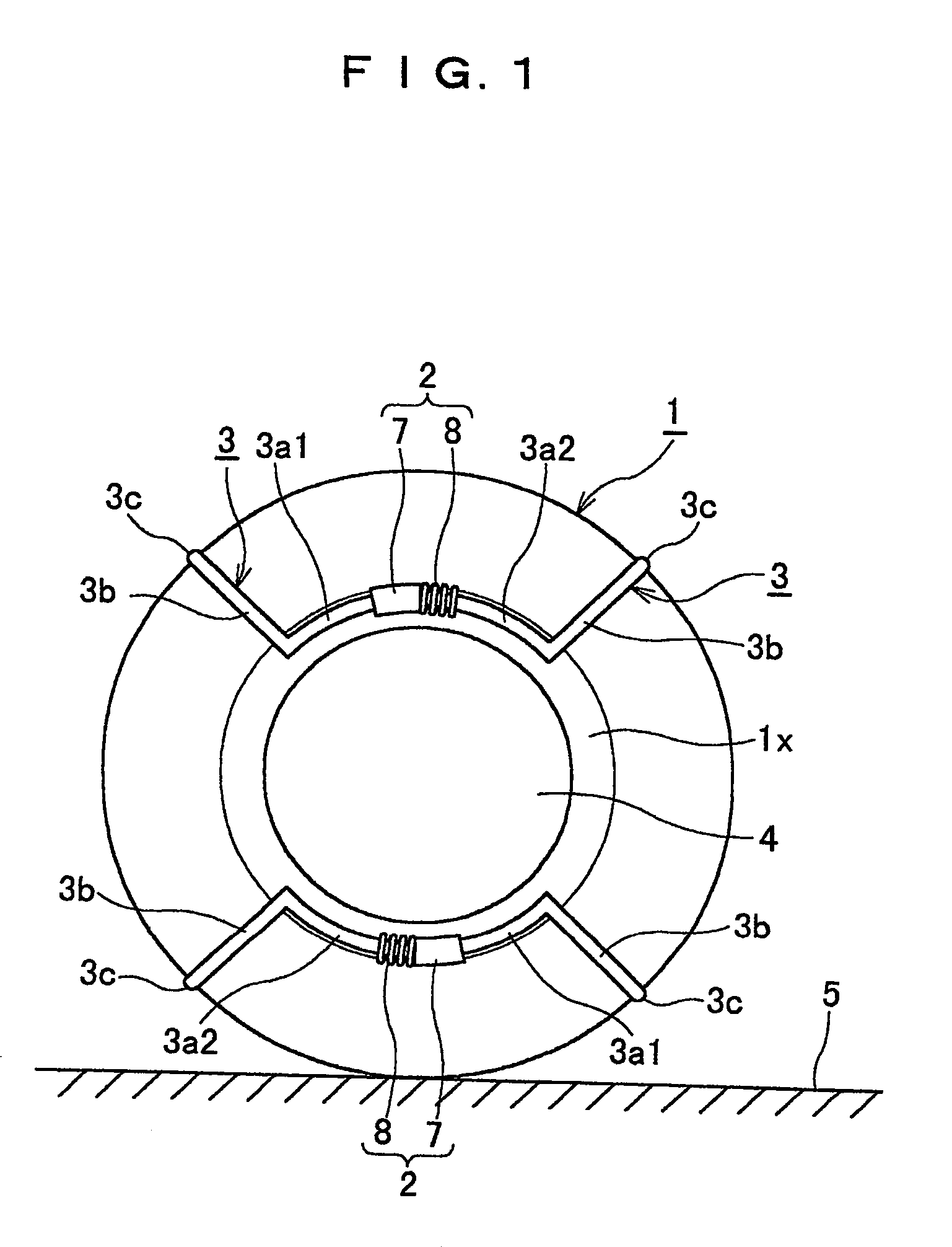
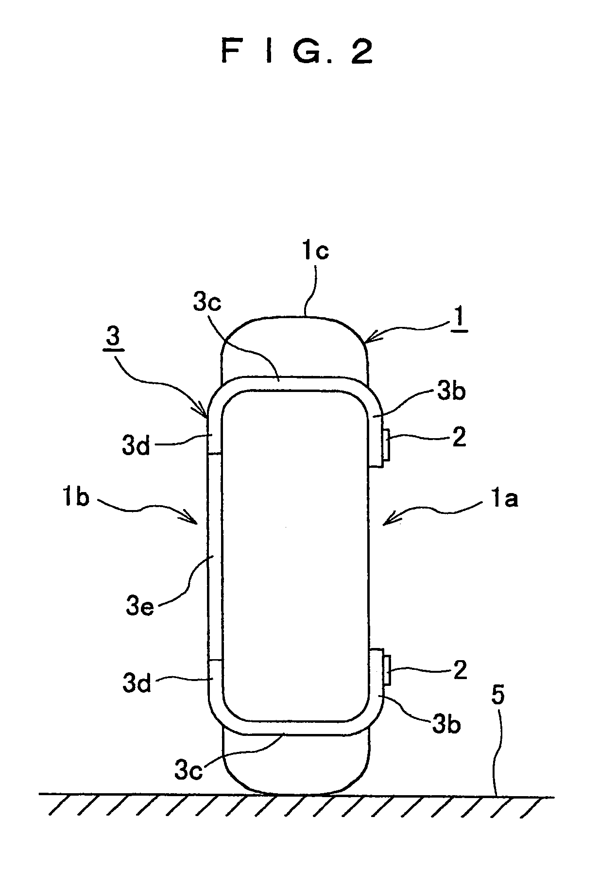
[0034]Referring to FIGS. 1 to 5, a slip-preventing device according to a first embodiment of the invention has a plurality of arm frames 3. Each of the arm frames 3 has a shape contacting with an inside surface, a ground-touching surface and an outside surface of a tire 1. Each of the arm frames 3 has a link unit 2 provided at an outer side of the tire 1. The link unit 2 links the arm frames 3 with each other. In detail, the slip-preventing device has two arm frames 3. Each of the arm frames 3 has a pair of outer side components 3a1 and 3a2, a pair of crossing components 3b, 3c, 3d and the link unit 2. Each of the outer side components 3a1, 3a2 has essentially an arc shape that extends circumferentially along part of an inner periphery of an outer sidewall 1a constituting the outside surface of the tire 1. The outer side component 3a1, 3a2 is supported while contacted with the sidewall 1a of the tire 1 near a beat 1x. A pair of the outer side components 3a1, 3a2 are arranged at a fi...

second embodiment

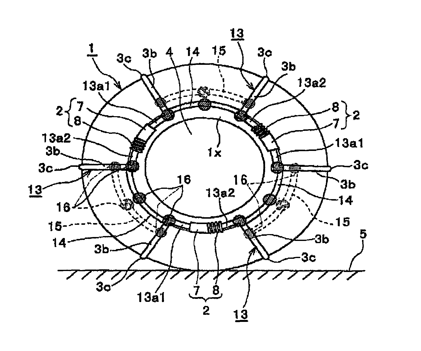
[0043]As shown in FIG. 7, the second embodiment of the slip-preventing device uses three arm frames 13. Each of the arm frames 13 has basically the same structure as the arm frame 3 of the first embodiment. In detail, each of the arm frames 13 has a pair of outer side components 13a1 and 13a2, a pair of crossing components 3b, 3c, 3d and an inner side component 15. A pair of the outer side components 13a1, 13a2 are arranged on the sidewall 1a of the tire 1 such that base ends thereof are spaced apart at an angular interval of about 70 degrees in the circumferential direction of the tire 1. Each of the outer side components 13a1, 13a2 in itself has an arc shape extending in the circumferential direction of the sidewall 1a at an angle of about 25 degrees. The pair of the crossing components 3b, 3c, 3d is arranged at an angle of about 70 degrees. The inner side component 15 has an arc shape extending about 70 degrees. The arm frames 13 have their leading end portions of the pair of the...

third embodiment

[0047]Referring to FIG. 9, in the third embodiment, a torsion coil spring 16d as an elastic body is interposed between the connecting portion 16a and the connecting portion 16b along their joint surface. The torsion spring 16d has its center coil portion fitted on an outer circumference of an axis of the pin 16c. The torsion spring 16d has it one end fixed on the connecting portion 16a and the other end on the connecting portion 16b. The torsion spring 16d applies springy force on the outer side components 13a1, 13a2 and the crossing components 3b, 3c, 3d to keep them in substantially a perpendicular state or an initial state. The torsion spring 16d applies springy force on the crossing components 3b, 3c, 3d and the inner side component 15 to keep them in substantially a perpendicular state or an initial state. The torsion spring 16d applies urging force on the inner side component 15 and the reinforcing rod 14 to keep them in an arc state or an initial state. The third embodiment o...


PUM


Abstract

A slip-preventing device of a tire has a plurality of arm frames each of which is contacted with an inner sidewall, a tread and an outer sidewall of the tire. The arm frame has a link unit at a side of the outer sidewall of the tire. The arm frames are linked with each other by the link units.

Description

BACKGROUND OF THE INVENTION[0001]1. Field of the Invention[0002]This invention relates to a slip-preventing device for a tire that is attached to the tire of an automobile or the like so as to prevent the tires from slippage on a snow-covered road or a frozen road in winter.[0003]2. Description of the Related Art[0004]Conventionally, a variety of tire chains are supplied to improve a slip preventing or traction effects of normal tires. Generally, it is very laborious and takes much time to fit the conventional tire chains on the tires. Such work is very complicated and troublesome for users who handle the tire chains once or twice a year. Attaching the tire chains needs much time for such users. Particularly, the fitting work becomes more difficult under bad condition such as the work on a snow-covered road. Moreover, the attaching work is very hard for users who are weak such as women or the like.BRIEF SUMMARY OF THE INVENTION[0005]It is an object of the invention to provide a slip...

Claims


Application Information

Patent Timeline
Patent Type & Authority Patents(United States)
IPC IPC(8): B60C27/00B60C27/04B62D21/11
CPCB60C27/04
Inventor SAKAKIBARA, KOUICHI
Owner SAKAKIBARA KOUICHI
Why Eureka
Try Eureka