Centralizer system for insulated pipe

a centralizer system and insulated pipe technology, applied in the direction of drilling pipes, drilling rods, drilling casings, etc., can solve the problems of unsatisfactory exacerbate the slippage of centralizers, and do not disclose suitable means for preventing axial slippage of centralizers

Active Publication Date: 2006-08-29
NAT COUPLING
View PDF17 Cites 32 Cited by
  • Summary
  • Abstract
  • Description
  • Claims
  • Application Information

AI Technical Summary

Benefits of technology

[0018]One or more interlocking members interlock the internal cylindrically shaped surfaces of the clamp with respect to the one or more metallic centralizers to thereby prevent axial movement of the one or more metallic centralizers with respect to the metallic pipe. The one or more interlocking members may comprise at least one radially inwardly directed projection and at least one radially outwardly directed projection whereby the radially inwardly directed projection and the radially outwardly directed projection are axially spaced with respect to each other. In one embodiment, the one or more interlocking members prevent axial movement of the one or more metallic centralizers with respect to the metallic pipe but permit at least limited rotation of the one or more centralizers with respect to the metallic pipe.

Problems solved by technology

Due to the high stresses involved, over time undesirable axial slippage of the centralizers may occur with respect to the non-fixed riser connection or stress joint.
Other problems with the non-fixed connections that may exacerbate the slippage of the centralizer include corrosion and / or galvanic action between for instance, the wellhead and the non-fixed riser connection or stress joint wherein the wellhead and centralizers may comprise steel and the stress joint may comprise titanium and / or steel.
The above cited prior art does not disclose suitable means for prevention of axial slippage of centralizers in a stress joint which may be subject to substantial forces as well as to corrosion and / or galvanic action.

Method used


Image

  • Centralizer system for insulated pipe
  • Centralizer system for insulated pipe
  • Centralizer system for insulated pipe

Examples


Embodiment Construction

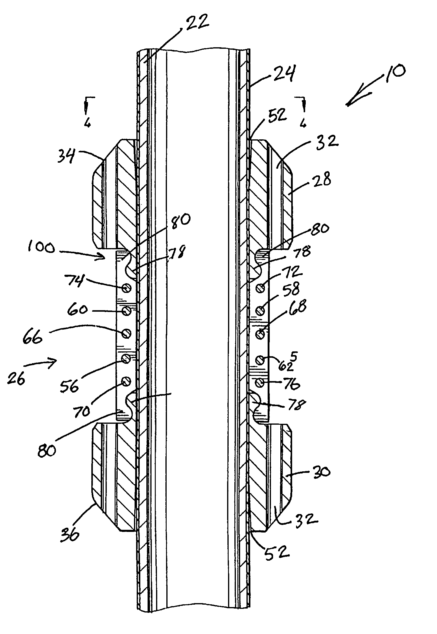
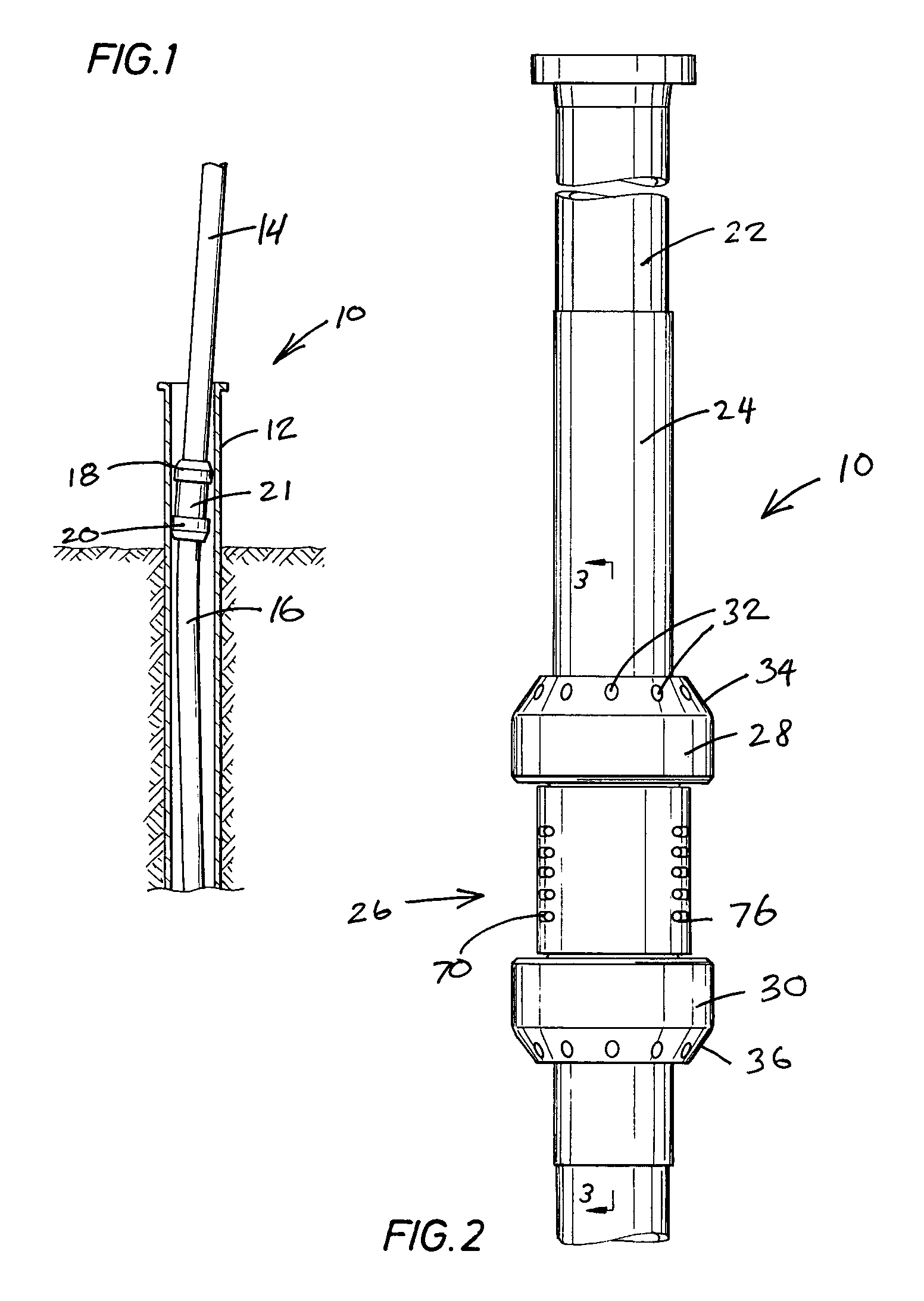
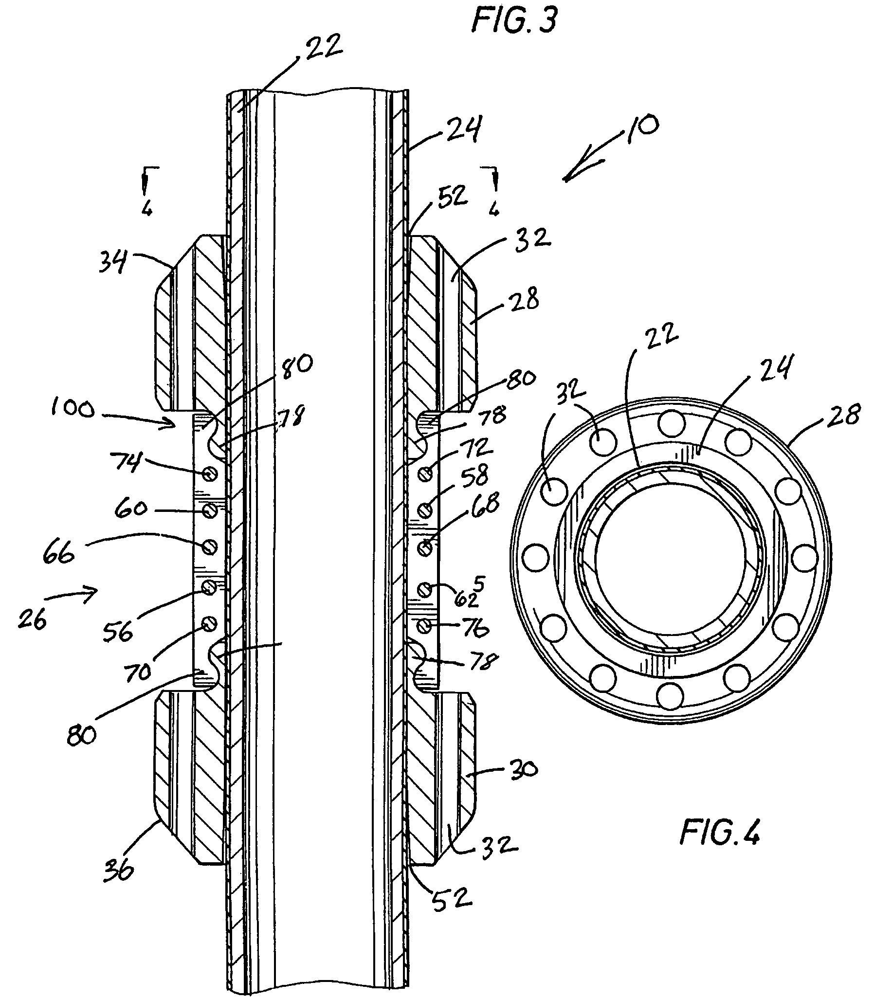
[0030]Referring now to the drawings and, more specifically, to FIG. 1, there is shown an example of non-fixed riser connection comprising centralizer system 10 interconnected to wellhead 12 in accord with the present invention. The bending of upper pipe / riser section 14 and lower pipe / riser section 16 above and below centralizers 18 and 20 is the result of loads as applied various types and portions of floating platforms and production vessels which may include without limitation, as examples only, tension leg platforms, spars, barges, ships, and the like (see for Example U.S. Pat. No. 4,185,694) referenced hereinbefore. The pipe which may include upper and lower sections 14 and 16 for insertion into wellhead 12 or a marine receptacle may be referred to herein as a stress joint, and may comprise a titanium stress joint. Due to the various types of floating platforms involved, the types of forces involved with non-fixed riser connections may vary considerably. While pipe / riser sectio...


PUM


Abstract

A centralizer system is provided for use in a marine riser system with an insulated pipe, which may be a titanium stress joint. The centralizer system utilizes one or more centralizers mounted such that insulation material is provided in an annulus between the one or more centralizers and the stress joint. A clamp is utilized to axially affix either one centralizer or multiple centralizers to the stress joint. The clamp is comprised of a plurality of sections with cylindrical interior surfaces which are tightened together using fasteners. The cylindrical interior surfaces avoid damage to the insulation layer which may be elastomeric. The clamp and each centralizer have radially directed projections thereon which interlock the clamp with each centralizer. Because the clamp is axially affixed, the centralizer is then also axially affixed. In one embodiment, the centralizer is axially moveable to a desired axial position prior to being interlocked to the tightened clamp.

Description

BACKGROUND OF THE INVENTION[0001]1. Field of the Invention[0002]The present invention relates generally to high-load centralizer systems and, more specifically, provides a system for securing one or more centralizers to a pipe coated with elastomeric or other suitable insulation material which in one preferred embodiment may be utilized as non-fixed riser interconnection or stress pipe riser interconnection between a floating platform and / or a subsea wellbore.[0003]2. Description of the Prior Art[0004]Marine risers have been utilized in the past with non-fixed riser interconnections, also referred to herein sometimes as stress joints and / or keel joints, which provide riser interconnections to floating platforms and / or drill ships and / or wellheads. A stress joint utilized adjacent the floating platform may sometimes be referred to herein as a keel joint because it extends through the bottom or the keel of the platform or other marine vessel. As used herein floating platform may refer...

Claims


Application Information

Patent Timeline
Patent Type & Authority Patents(United States)
IPC IPC(8): E21B17/10
CPCE21B17/1085E21B17/01
Inventor BAXTER, CARL F. G.CALDWELL, CHRISTOPHER S.ROSE, JR., ROBERT E.DYER, BRENT L.BEARD, MICHAELAVERY, ROY DANIEL
Owner NAT COUPLING
Why Eureka
Try Eureka