
Wellhead assembly with pressure actuated seal assembly and running tool

a technology of sealing assembly and running tool, which is applied in the direction of sealing/packing, drilling pipes, borehole/well accessories, etc., can solve the problems of complex and expensive hydraulically powered running tools

Active Publication Date: 2006-08-29
DRIL QUIP
View PDF9 Cites 32 Cited by
  • Summary
  • Abstract
  • Description
  • Claims
  • Application Information

AI Technical Summary

Benefits of technology

[0012]A split lock ring may expand by rotation of the running string to move a setting sleeve to a locked position, while rotation of the running string in an opposing direction moves the setting sleeve to an unlocked position. An anti-rotation key may be provided for allowing a running string to be rotated and the setting sleeve moved axially without rotating either the running tool or the hanger. A retaining ring carried on the setting sleeve may secure the seal assembly in place when the hanger is being run in a well, then release the fully installed seal assembly. Rotation of the running string to the right also releases the seal assembly to move downward.
[0013]A running tool is provided for setting a seal assembly between a wellhead housing and a tubular hanger for supporting a tubular string in a well. The running tool includes a running tool body for lowering the seal assembly within wellhead housing, and a setting piston supported on the running tool body for moving the seal assembly axially to a set position, such that the seal assembly may be lowered and energized by the application of fluid pressure to the setting piston. Fluid pressure in the assembly surrounding the running string acts on the setting piston for moving the seal assembly to the set position. The setting piston seals on a radially inward surface and a radially outward surface of the tool body. An elastomeric seal on the seal assembly is preferably also provided for sealing between the wellhead housing and the hanger, and allows fluid pressure to also act directly on the seal assembly. A locking piston supported on the running tool may lock the seal assembly to the hanger.

Problems solved by technology

Many hydraulically powered running tools are, however, complex and expensive.

Method used


Image

  • Wellhead assembly with pressure actuated seal assembly and running tool
  • Wellhead assembly with pressure actuated seal assembly and running tool
  • Wellhead assembly with pressure actuated seal assembly and running tool

Examples


Embodiment Construction

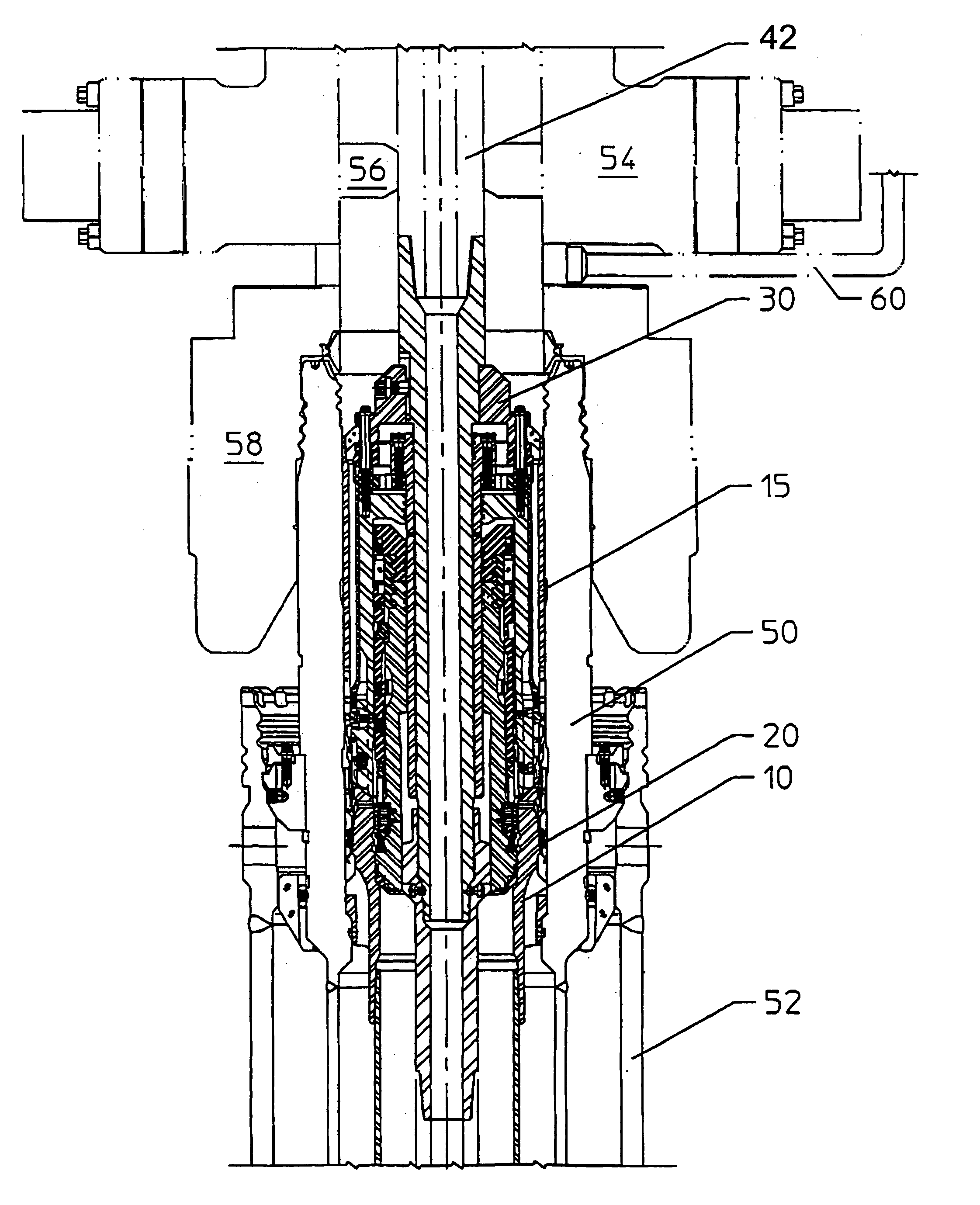
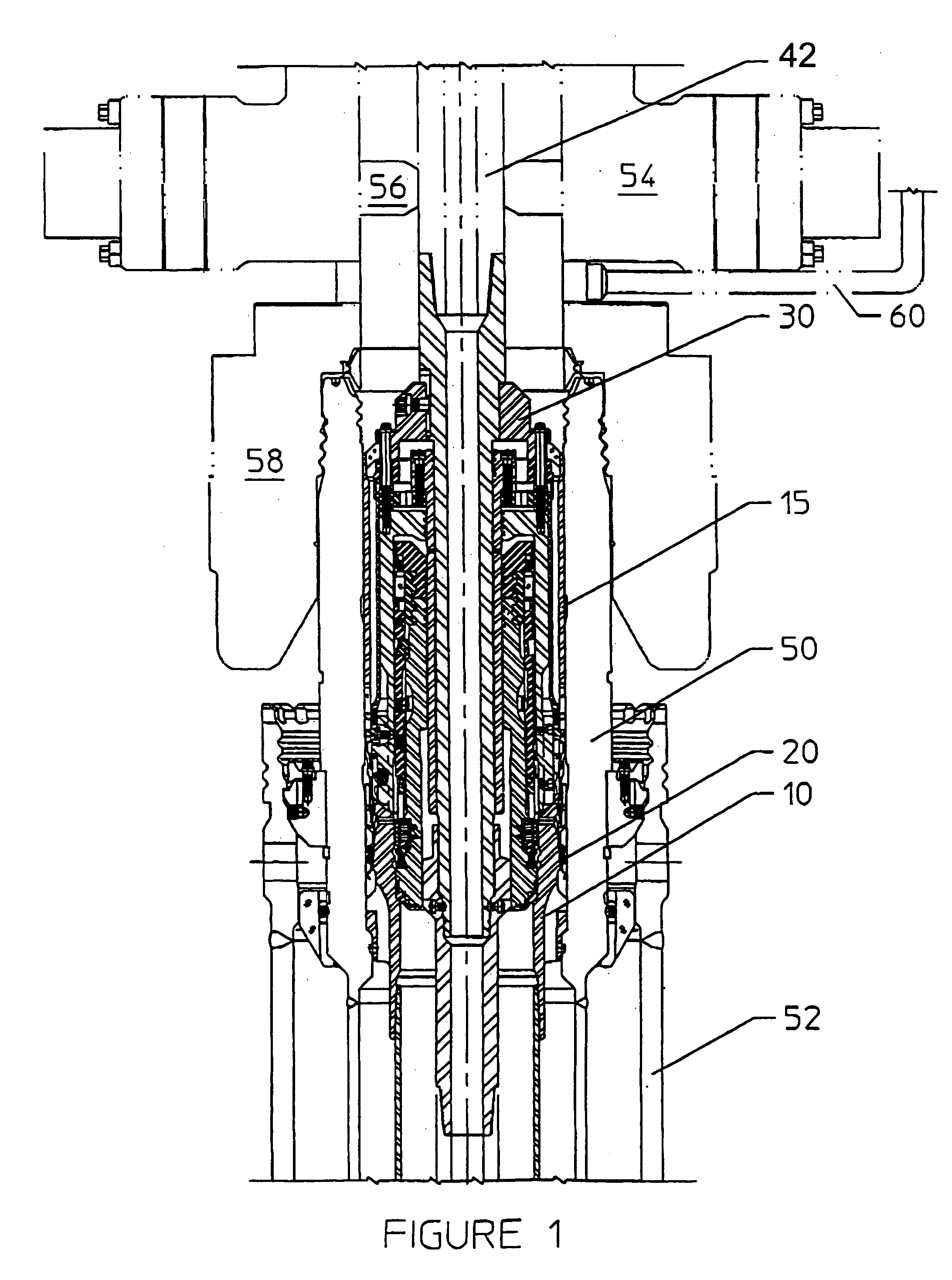
[0020]FIG. 1 illustrates a subsea wellhead housing 50, an outer conductor pipe 52, a blowout preventor (BOP) 54 above the wellhead with rams 56, and connector 58 connecting the BOP 54 to the wellhead housing 50. A plurality of the choke and kill lines 60 may conventionally extend from the surface to the BOP, and may be used to operate the casing hanger running tool, as disclosed herein. Separate hydraulic lines (not shown) may extend from the surface to power the rams of the BOP.

[0021]FIG. 1 shows the casing hanger 10 landed on a subsea wellhead housing 50, with the seal assembly 20 fully set and locked in place. Subsea wellheads and casing hangers are used in increasingly high temperature and / or pressure environments. A preferred all metal seal may accommodate these requirements, but the force required to install the seal is also higher. The present invention provides a setting piston to assist in providing the required setting force to fully set the seal.

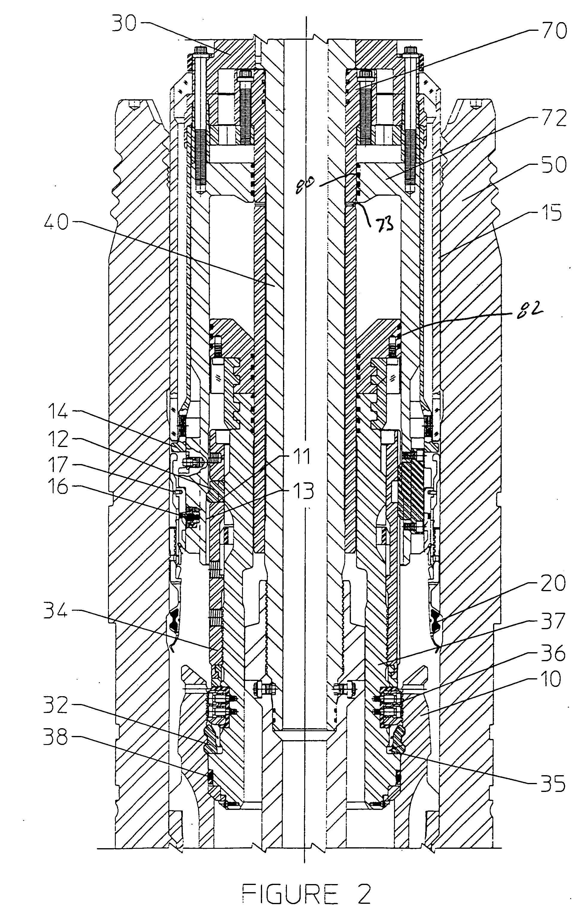
[0022]The running tool 30 ...


PUM


Abstract

A subsea well assembly includes a wellhead housing 50 having a cylindrical inner sealing surface and a tubular hanger 10 having a tapered external sealing surface. The running tool 30 includes a central stem 40 connected to the running string. A setting piston 72 is responsive to fluid pressure in the annulus about the running string, and has a radially outer surface and a radially inner surface each for sealing with the running tool body. Fluid pressure to set the seal assembly may be applied to the setting piston through an annulus about the running string, and may also act directly on an initially set seal assembly 20.

Description

RELATED CASEThe present application claims the benefit of Application 60 / 476,933 filed Jun. 10, 2003.FIELD OF THE INVENTION[0001]The present invention relates to wellhead equipment and, more particularly, to a wellhead assembly with a tubular hanger adapter to be lowered in a well, then landed within and sealed to a subsea wellhead housing, thereby suspending a tubular string from the wellhead housing, with the hanger sealed to the wellhead housing.BACKGROUND OF THE INVENTION[0002]A wellhead housing may be located on the sea floor, so that a casing string may extend downward from the wellhead housing into the well, with the casing string supported in the wellhead housing by a casing hanger. A seal assembly may be installed between the casing hanger at the upper end of the casing string and the wellhead housing. The operator may install the casing string and seal assembly remotely, and in seas of considerable depths.[0003]Running tools have been developed for delivering forces to set...

Claims


Application Information

Patent Timeline
Patent Type & Authority Patents(United States)
IPC IPC(8): E21B29/12E21B23/04E21B33/035E21B33/043
CPCE21B23/04E21B33/043E21B33/035E21B23/042
Inventor REIMERT, LARRY
Owner DRIL QUIP
Learn More