
Temperature compensation systems and methods for use with read/write heads in magnetic storage devices

a magnetic storage device and temperature compensation technology, applied in the direction of heating types, instruments, optical radiation measurement, etc., can solve the problems of not being able to place the head at the least distance from the disk media, and conventional techniques employed to detect the temperature on which the fhc is based do not typically give an actual and accurate reading

Active Publication Date: 2006-08-29
TEXAS INSTR INC
View PDF10 Cites 49 Cited by
  • Summary
  • Abstract
  • Description
  • Claims
  • Application Information

AI Technical Summary

Benefits of technology

The patent describes methods and systems for controlling the temperature of a resistive element in a read / write head of a magnetic data storage device. The resistive element can vary its voltage based on its temperature, which can affect its performance. The patent proposes a system that detects the voltage across the resistive element and compares it to a predetermined value to determine any deviation. An altered power is then applied to the resistive element to control its temperature and ensure optimal performance. The technical effect of this patent is to provide a more precise and efficient way to control the temperature of a resistive element in a read / write head of a magnetic data storage device.

Problems solved by technology

However, since PTP occurs during operation, the heads cannot be placed at the least distance from the disk media, lest they collide with the disk media as they heat-up during use.
Unfortunately, conventional techniques employed to detect the temperature on which the FHC is based do not typically give an actual and accurate reading at the most important point in the FHC process, the head-disk interface (HDI).

Method used


Image

  • Temperature compensation systems and methods for use with read/write heads in magnetic storage devices
  • Temperature compensation systems and methods for use with read/write heads in magnetic storage devices
  • Temperature compensation systems and methods for use with read/write heads in magnetic storage devices

Examples


Embodiment Construction

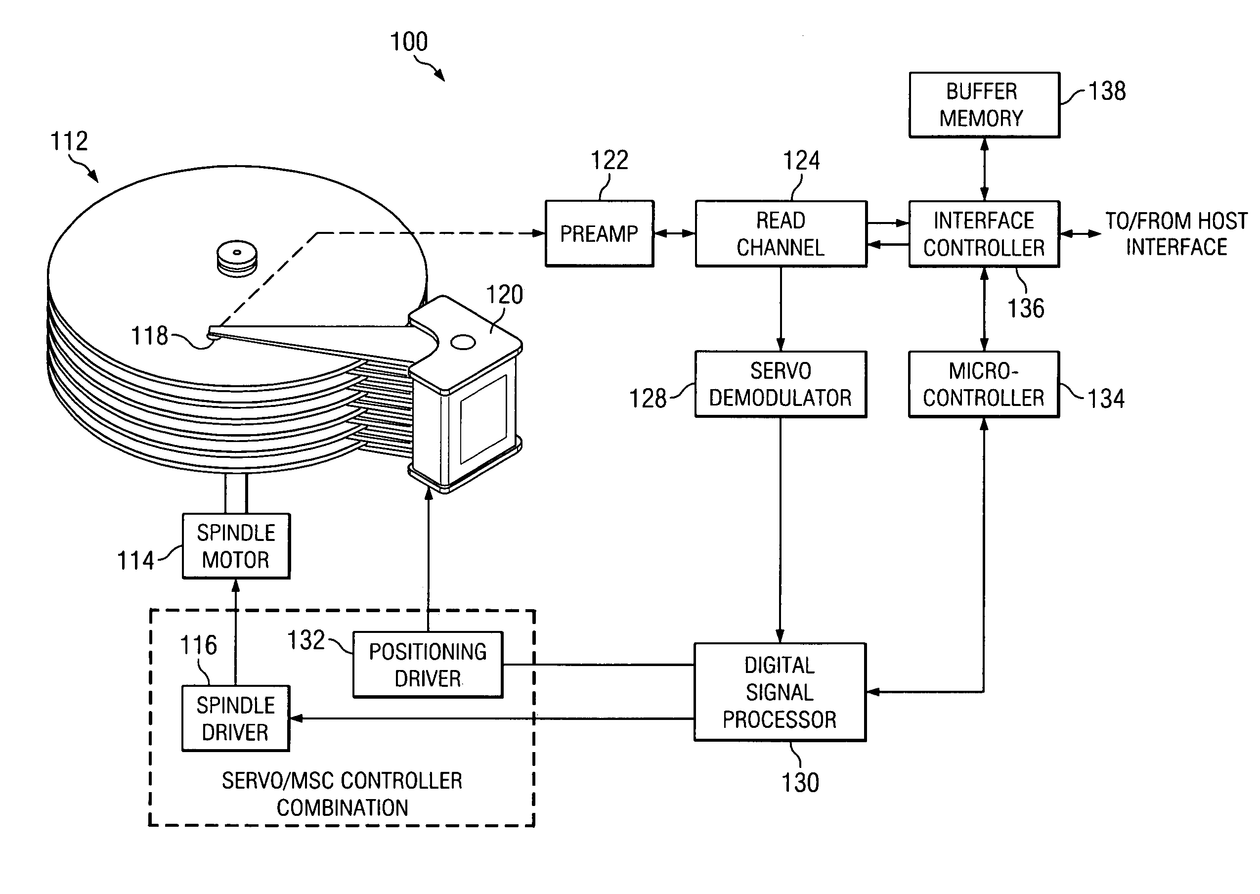
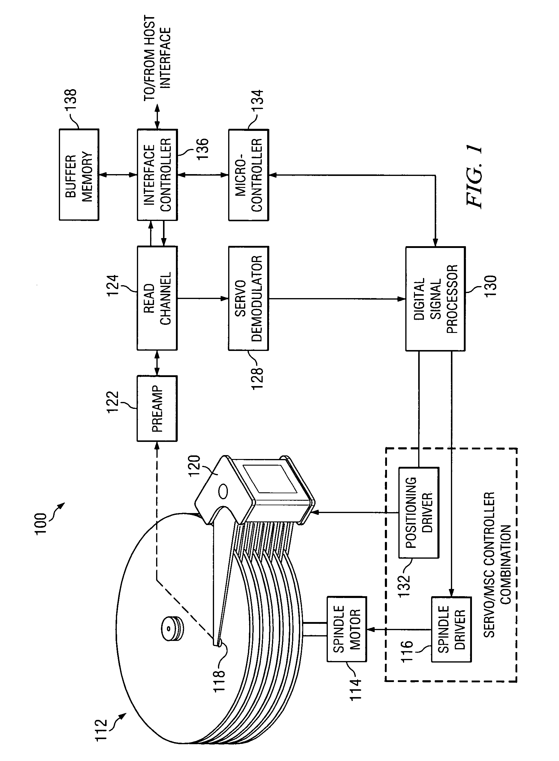
[0015]Referring initially to FIG. 1, illustrated is a block diagram of a generic disk drive system 100, which represents one general environment that may incorporate systems and methods according to the principles disclosed herein. The system 100 includes a magnetic media disk stack 112 that is rotated by a spindle motor 114 and spindle driver circuit 116. A data head 118 is locatable along selectable radial tracks (not shown) of the disk stack 112 by a voice coil motor (VCM) 120.

[0016]In one embodiment, both sides of each disk in the disk stack 112 are provided with magnetic recording media in the form of an annular pattern of concentric data tracks having an inner diameter and an outer diameter. The radial tracks may contain magnetic states that represent information about the tracks, such as track identification data, location information, synchronization data, as well as user data, and so forth. The head 118, which includes read and write transducers (that may be a magneto-resis...


PUM

PropertyMeasurementUnit
temperatureaaaaaaaaaa
voltageaaaaaaaaaa
poweraaaaaaaaaa

Abstract

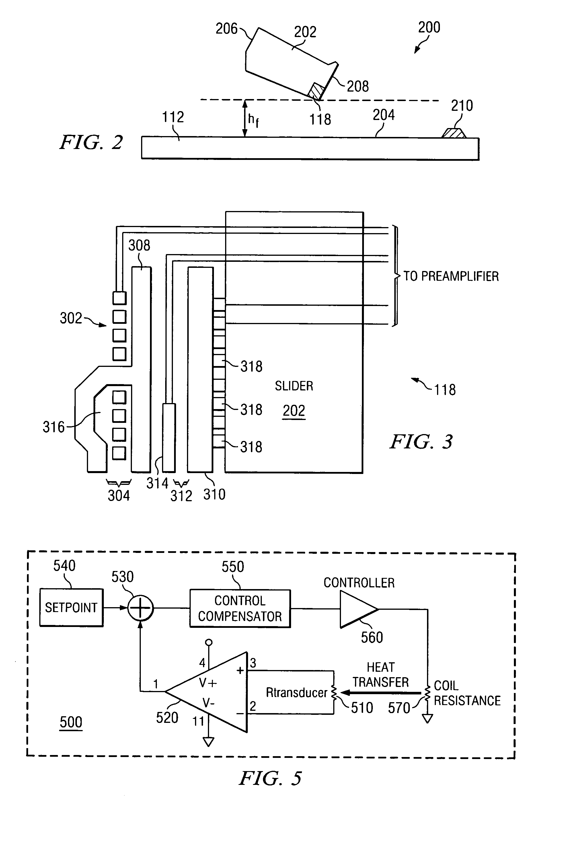
Disclosed herein are methods and systems for sensing and controlling the temperature of a resistive element configured for use in a read / write head of a magnetic data storage device. In one embodiment, a method includes detecting a voltage across the resistive element, where the voltage varies as a function of a temperature of the resistive element. The method also includes comparing the voltage to a predetermined value to determine a variation of the voltage from the predetermined value, and then altering a power applied to the resistive element based on the variation. In this exemplary embodiment, the temperature of the resistive element is then controlled as a function of the altered applied power.

Description

RELATED APPLICATION[0001]This application claims priority under 35 USC § 119(e)(1) of provisional application Ser. No. 60 / 499,678, filed Sep. 2, 2003.TECHNICAL FIELD[0002]Disclosed embodiments herein relate generally to read / write heads in magnetic storage devices, and more particularly to temperature compensation systems and methods for use with such read / write heads to sense and regulate the temperature of resistive elements within the read / write heads.BACKGROUND[0003]With mass data storage currently falling into the terabyte range, mass data storage devices have become increasingly employed in computers and large data storage systems. Also due to the increasing amount of data to be stored, data read and write speeds have necessarily had to be improved. Such mass data storage devices include tape drives, as well as hard disk drives that have one or more spinning magnetic disks onto which data is recorded for storage and subsequent retrieval. Hard disk drives may be used in many ap...

Claims


Application Information

Patent Timeline
Patent Type & Authority Patents(United States)
IPC IPC(8): F24F11/053G01J5/00G01K5/00G11B5/03H01C7/06F24F11/76G01K3/00G11B5/00H01C7/00
CPCG01K3/00G11B5/5565G11B2005/0018
Inventor SHEPEREK, MICHAEL W.BLOODWORTH, BRYAN E.
Owner TEXAS INSTR INC
Learn More