Pneumatically operated fluid filled engine mount

a technology of fluid filling and engine, applied in the direction of machine supports, jet propulsion mountings, shock absorbers, etc., can solve the problems of increasing the number of components, and idling vibrations or other medium frequency and medium amplitude vibrations, so as to achieve excellent damping effect, excellent damping effect, and excellent damping

Inactive Publication Date: 2006-08-29
SUMITOMO RIKO CO LTD
View PDF14 Cites 5 Cited by
  • Summary
  • Abstract
  • Description
  • Claims
  • Application Information

AI Technical Summary

Benefits of technology

[0012]It is therefore an object of the invention to provide a fluid-filled engine mount having a simple and novel structure, and which is capable of changing its damping characteristics in accordance with changes in input vibrations required to be damped, without needing complex components such as specific switch valves, driving means, control mechanism, or the like.

Problems solved by technology

However, this type of engine mount suffers from a problem that the damping effect is effective only to the narrow frequency range to which the orifice passage is tuned.
When driving, a vehicle tends to suffer from driving booming noises or other high frequency and small-amplitude vibrations, or engine shapes or other low frequency and large-amplitude vibrations.
When idling, the vehicle tends to suffer from idling vibrations or other medium frequency and medium amplitude vibrations.
Therefore, the number of components will increase, and the construction of the device will become extremely complex, making the assembly procedure become troublesome, and increasing the manufacturing costs.

Method used


Image

  • Pneumatically operated fluid filled engine mount
  • Pneumatically operated fluid filled engine mount
  • Pneumatically operated fluid filled engine mount

Examples


second embodiment

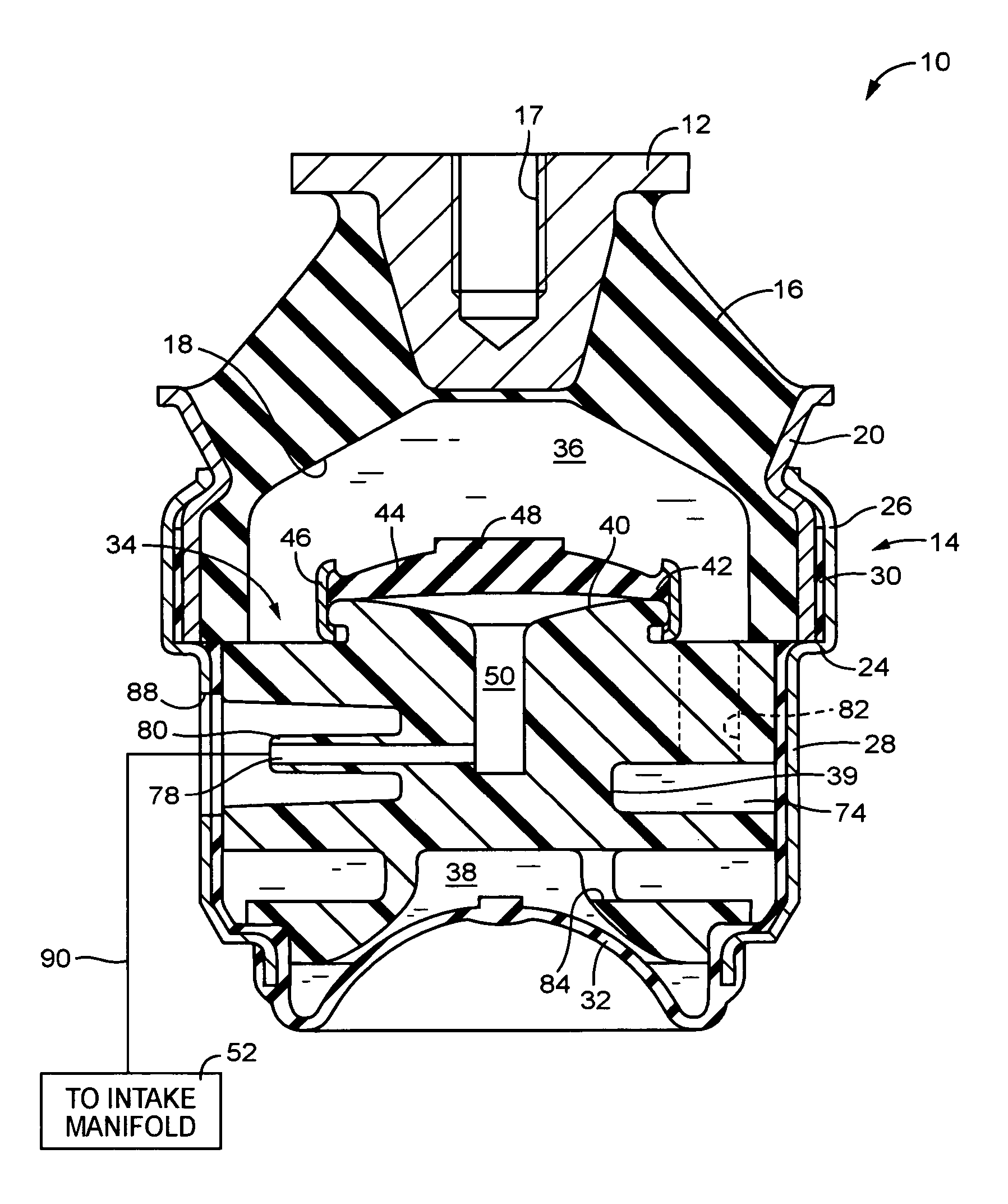
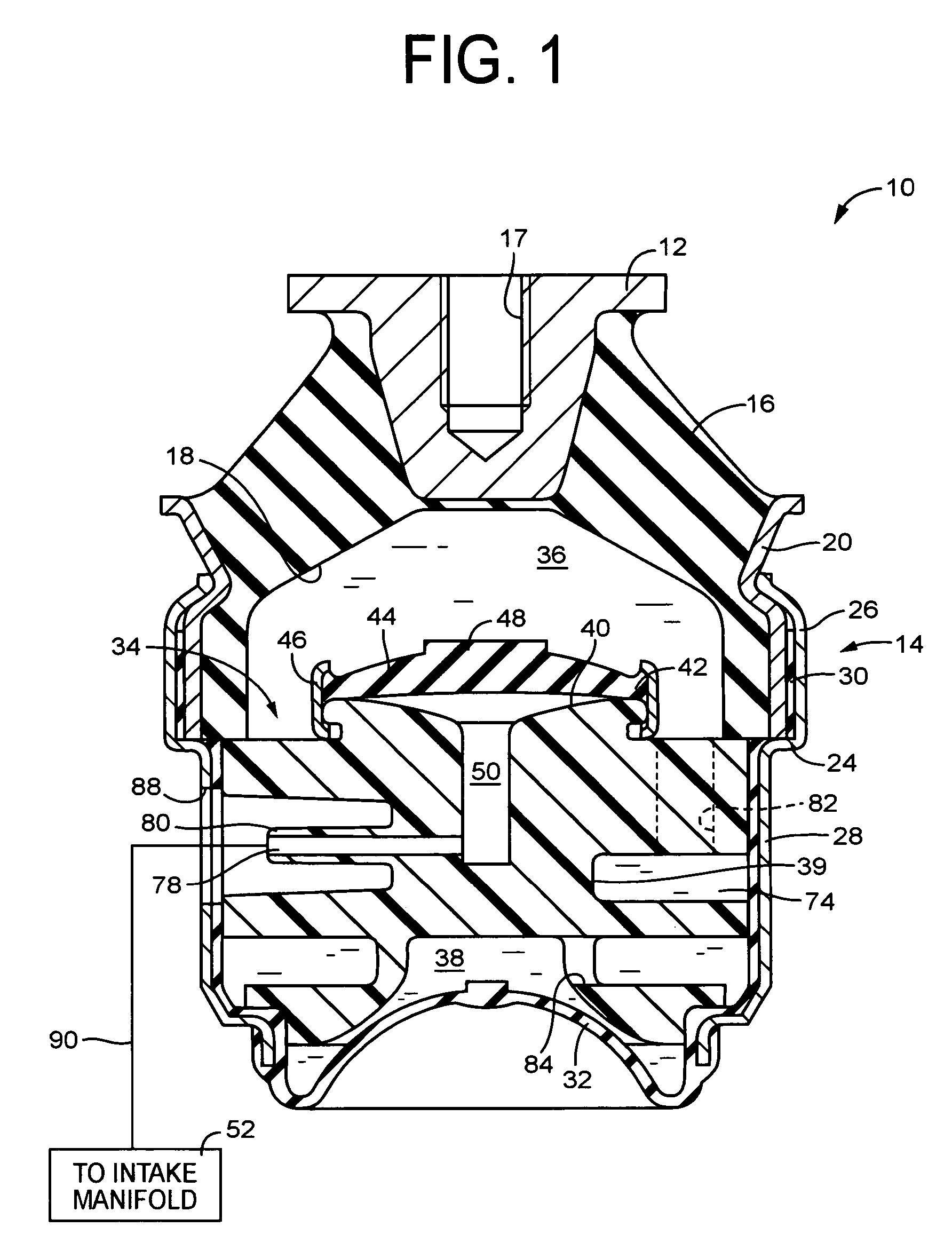
[0066]As shown in FIG. 4, the engine mount 100 constructed includes a cover member 92 assembled with the second mounting member 14 in order to cover the lower open end portion of the second mounting member 14. This cover member 92 cooperate with the diaphragm 32 to define therebetween the working air chamber 50 disposed on an opposite side across from the diaphragm 32 in relation to the equilibrium chamber 38. To this working air chamber 50 is connected an air conduit 90 directly connected to the intake manifold of the internal combustion engine.

first embodiment

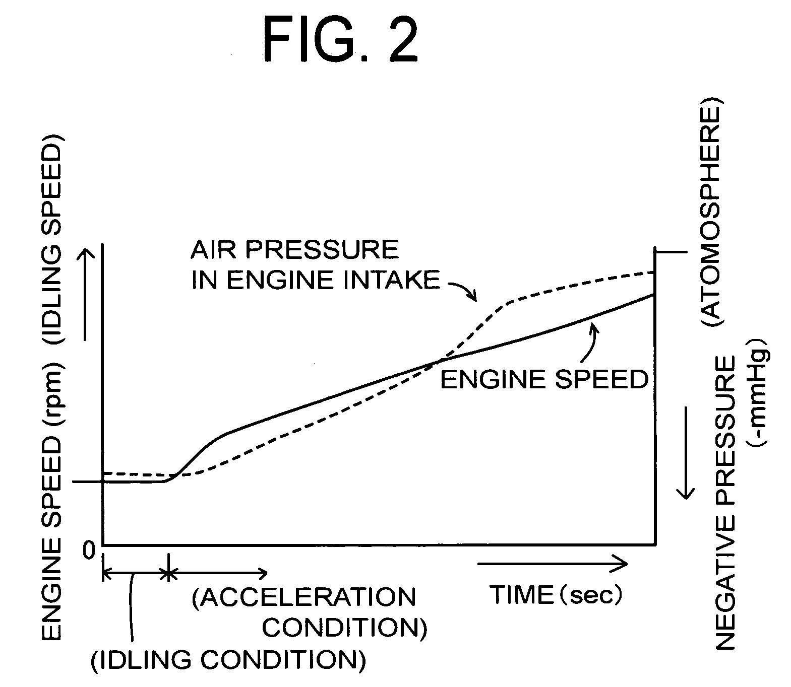
[0067]Like the engine mount 10 of the first embodiment, the engine mount 100 constructed as described above utilizes negative pressure generated in the air intake side of the engine whose value changes depending on the operating condition of the vehicle, whereby the engine mount 100 is capable of automatically changing its damping characteristics in accordance with input vibrations varying depending on the operating conditions of the vehicle.

[0068]That is, during idling condition of the vehicle, negative pressure having a value greater than the threshold value is applied to the pressure-receiving chamber 36 via the equilibrium chamber 38 and the orifice passage 74, so that the rubber elastic plate 44 undergoes large elastic deformation so as to be suctioned toward the inside of the pressure-receiving chamber 36, thereby being held in a state of high dynamic spring constant. With this arrangement, pressure fluctuation generated in the pressure-receiving chamber 36 is never absorbed b...

third embodiment

[0071]Meanwhile, in the engine mount 150 constructed according to the invention as shown in FIG. 5, the partition member 34 separating the pressure-receiving chamber 36 and the equilibrium chamber 38 is formed of an upper partition plate 94 and an lower partition plate 96, which are made of metal, and are mutually superimposed on and bonded to each other in a direction of the wall thickness thereof.

[0072]The upper and lower partition plates 94, 96 cooperate to each other to define therebetween the orifice passage 74 that extends over a length somewhat smaller than the entire way around a circumference of the partition member 34. One of opposite ends of the orifice passage 74 is communicated with the pressure-receiving chamber 36 through a first communication hole 98 formed through the upper partition plate 94, while the other end of the orifice passage 74 is communicated with the equilibrium chamber 38 through a second communication hole 99 formed through the lower partition plate 9...


PUM


Abstract

A fluid filled engine mount including: a pressure-receiving chamber and an equilibrium chamber connected via an orifice passage tuned to a frequency band of engine idling vibrations; an orifice control member operable by means of negative pressure exerted from an external space so as to restrict flow of the fluid through the orifice passage when an absolute value of the exerted negative pressure is greater than a predetermined value; and a negative pressure conduit of direct connection type, adapted to always introduce negative pressure available from an air intake port of an internal combustion engine to the orifice control member.

Description

[0001]The disclosure of Japanese Patent Application No. 2003-094220 filed on Mar. 31, 2003 including the specification, drawings and abstract is incorporated herein by reference in its entirety.BACKGROUND OF THE INVENTION[0002]1. Field of the Invention[0003]The present invention relates generally to a fluid-filled engine mount capable of exhibiting vibration damping effect or action based on resonance or flow action of non-compressible fluid sealed therein. More specifically, the present invention is concerned with such a fluid-filled engine mount of novel structure that is capable of providing excellent vibration damping or isolating effect against input vibration over a wide frequency band by automatically controlling its damping characteristics in accordance with fluctuation of vibrations to be damped, without needing complicated control means such as switch valves and control devices.[0004]2. Description of the Related Art[0005]Vibrations (including noises induced by the vibrati...

Claims


Application Information

Patent Timeline
Patent Type & Authority Patents(United States)
IPC IPC(8): F16F13/00B60K5/12F16F13/26
CPCF16F13/264F16F2230/183
Inventor ICHIKAWA, HIROYUKIAKASA, SYOUJIHAMADA, MASAAKIOGAWA, YUICHI
Owner SUMITOMO RIKO CO LTD
Why Eureka
Try Eureka