
Position detector

a detector and position technology, applied in the direction of instruments, transportation and packaging, using electrical/magnetic means, etc., can solve the problems of high cost, on/off behaviour, and unsuitable arrangement for continuous tray position determination

Inactive Publication Date: 2006-08-29
OCE TECH
View PDF13 Cites 3 Cited by
  • Summary
  • Abstract
  • Description
  • Claims
  • Application Information

AI Technical Summary

Benefits of technology

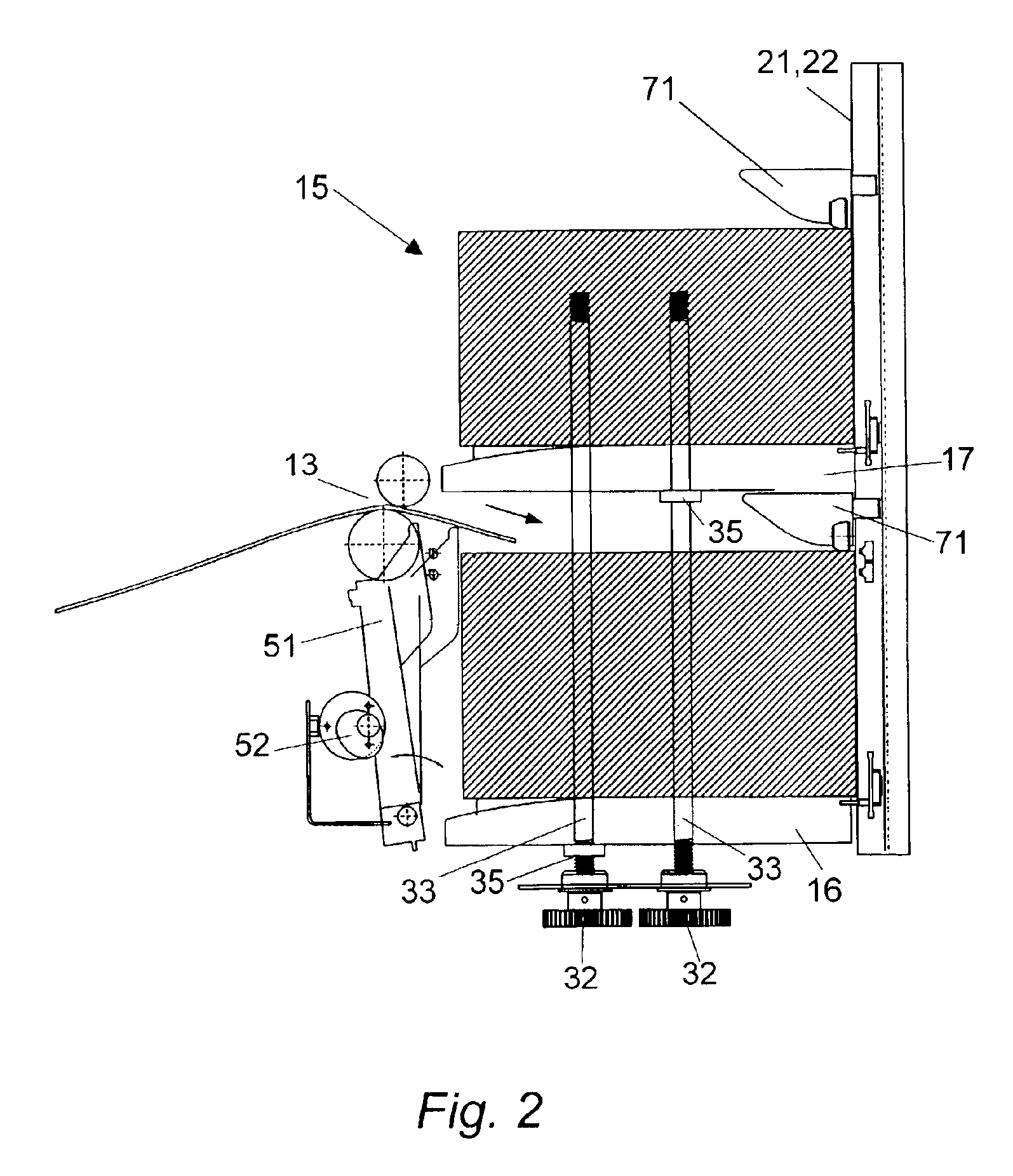
[0008]On this background, it is an object of the present invention to provide a sheet depositing device of the kind referred to initially, having a sensor arrangement which conveniently and reliably allows detection of the position of a plurality of sheet stacking elements, such as depositing platforms and sheet catchers.
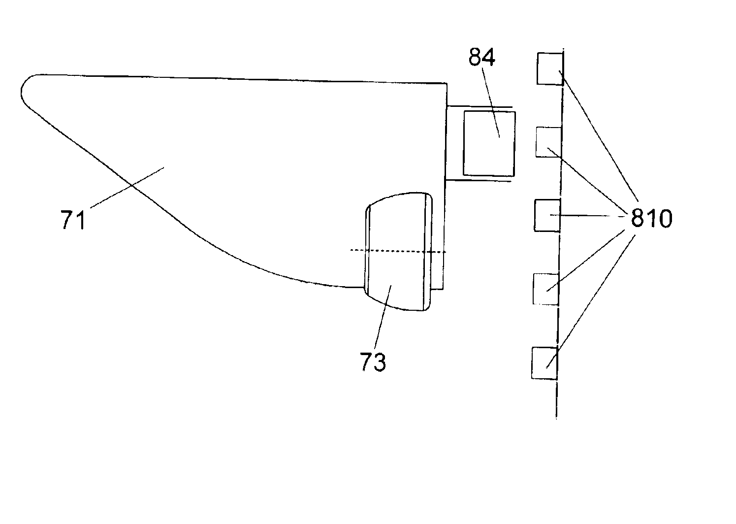
[0010]In accordance with an embodiment of the present invention, a sensor arrangement is provided wherein the active and passive elements are of a kind that interact through the use of electric or magnetic fields and wherein the active elements are positioned closely together in the array. This construction makes possible determining the position of the passive element at a higher resolution than the pitch of the active elements, because the passive element can be sensed by at least two active elements at a time and their readings can be interpolated.
[0011]A very basic form of interpolation would be to choose the position midway between two adjoining active elements, if both are activated by the passive element. A more sophisticated solution would be to calculate a weighted interpolation of the readings of the two adjoining active elements. Thus, in the present invention, less active elements per mm are required for a certain resolution, which brings down the cost, in addition to the fact that sensors as meant by the present invention are already cheaper than optical sensors of the related art.
[0012]Further, paper dust does not disturb measurements that rely on electric or magnetic fields, whereas the use of optical sensors does. By using an electric or magnetic sensor arrangement, the present invention provides a higher reliability and a higher measuring accuracy, so that the above-mentioned interpolation becomes also more reliable.
[0013]In a first embodiment of the present invention, the array of active elements comprises an array of conductive fields arranged in parallel to a conductive strip or a second array of conductive fields, and the passive element comprises a conductive plate. The measurement of this kind of sensor is based on the electrical capacity of the arrangement of a conductive field, the conductive plate and the conductive strip / array of fields. This is an extremely simple and cost-effective embodiment, which can easily be scaled down to give a high position resolution.
[0014]In a second embodiment of the present invention, the array of active elements comprises an array of Hall-effect sensors, and the passive element comprises a magnet. Hall sensors are inexpensive, relatively insensitive for dust and small enough to provide a good position resolution.

Problems solved by technology

However, the sensors are placed relatively far apart so that the arrangement is thus not suitable for a continuous tray position determination.
However, a disadvantage of optical sensors is that they have an on / off behaviour, such that the resolution of the position determination is equal to the pitch of the optical sensors.
If a high resolution is required, then many optical sensors must be mounted per mm, leading to high cost.
Further, optical sensors are quite sensitive to dust pollution.
Thus, sensor errors or failure are quite common when the optical sensors are used, the more so when small optical sensors are used to give a high resolution.

Method used


Image

  • Position detector
  • Position detector
  • Position detector

Examples


Embodiment Construction

[0030]In the present invention, expediently, the sheet depositing device is located at the output of a paper processing machine. The sheet depositing device of the present invention will hereafter be illustrated with a paper processing machine in the form of a printing apparatus. It is evident that the sheet depositing device could be operated together with any other type of paper processing apparatus, such as copiers, imaging devices, etc.

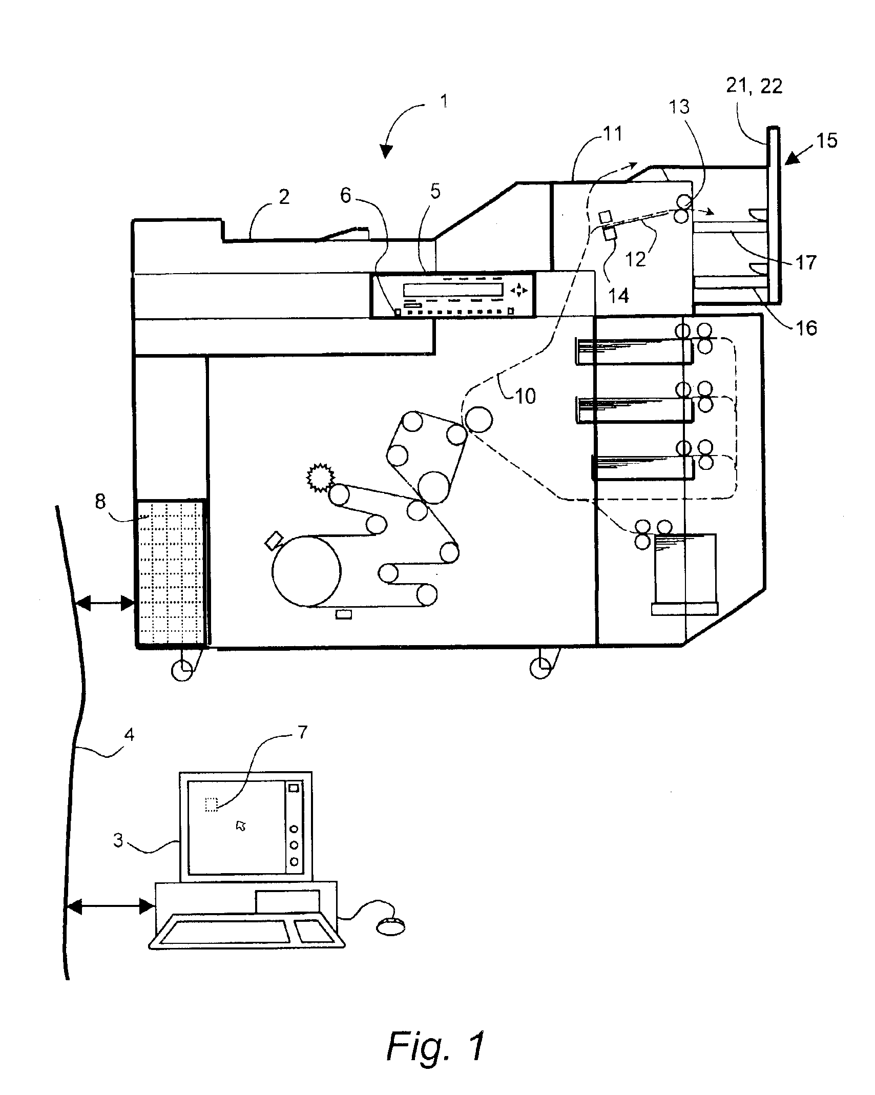
[0031]The printing apparatus 1 shown in FIG. 1 according to an embodiment of the present invention comprises means known for printing an image on a receiving sheet. These images for printing may be present on original documents which are fed to a scanning station 2 situated at the top of the printing apparatus 1. Images for printing can also be fed in digital form from a workstation 3 connected via a network 4 to a control device 8 of the printing apparatus 1. A printing cycle for copying an original set fed via the scanning station 2 is started b...


PUM


Abstract

A sheet depositing device for a sheet processing apparatus, includes a feeding section for sequentially feeding sheets or sets of sheets from the sheet processing apparatus, at least one sheet stacking element movable along a guide, for facilitating depositing the sheets or sets of sheets fed by the feeding section, and a sensor arrangement for detecting the position of a sheet stacking element along the guide. The sensor arrangement includes a stationary linear array of active elements and a passive element moving in unison with the sheet stacking element. The active and passive elements are of a kind that interact through the use of electric or magnetic fields. Examples of such sensors are an array of conductive fields arranged in parallel to a conductive strip or a second array of conductive fields, and a conductive plate connected to a capacitance meter; and an array of Hall-effect sensors and a magnet.

Description

[0001]The present application claims, under 35 U.S.C. § 119, the foreign priority benefit of European Patent Application No. 02076338.9 filed Mar. 29, 2002.BACKGROUND OF THE INVENTION[0002]1. Field of the Invention[0003]The present invention relates to a sheet depositing device for a sheet processing apparatus, comprising a feeding section for sequentially feeding sheets or sets of sheets from the sheet processing apparatus, at least one sheet stacking element movable along a guide, for facilitating the deposition of the sheets or sets of sheets fed by the feeding section in the sheet depositing device, and a sensor arrangement for detecting the position of a sheet stacking element along the guide, wherein the sensor arrangement includes a stationary linear array of active elements and a passive element moving in unison with the sheet stacking element.[0004]2. Discussion of Background Art[0005]An array of active sensors for determining a sheet stacking tray is known from U.S. Pat. N...

Claims


Application Information

Patent Timeline
Patent Type & Authority Patents(United States)
IPC IPC(8): B65H39/10B65H31/10B65H31/26G01B7/00B65H43/00G03G15/00
CPCB65H31/10B65H31/26B65H2511/20B65H2553/22B65H2553/414B65H2801/06B65H2220/03B65H2220/11B65H43/06
Inventor SPOORENBERG, CHRISTOPHORUS LAMBERTUSBRUGGELING, HENDRIK FREDERIK PAULBEEREN, ROEL PAUL MARIEROTHOFF, FRANCISCUS JOHANNES HERMANUS
Owner OCE TECH
Learn More