
Ventilation tube for a middle ear

a technology for ventilation tubes and eardrums, which is applied in the field of ventilating tubes for the middle ear, can solve the problems of increasing the difficulty of the operation, and the incisions of the eardrum normally self-heal within a relatively short tim

Inactive Publication Date: 2006-08-29
PERRY MICROTUBE
View PDF24 Cites 16 Cited by
  • Summary
  • Abstract
  • Description
  • Claims
  • Application Information

AI Technical Summary

Benefits of technology

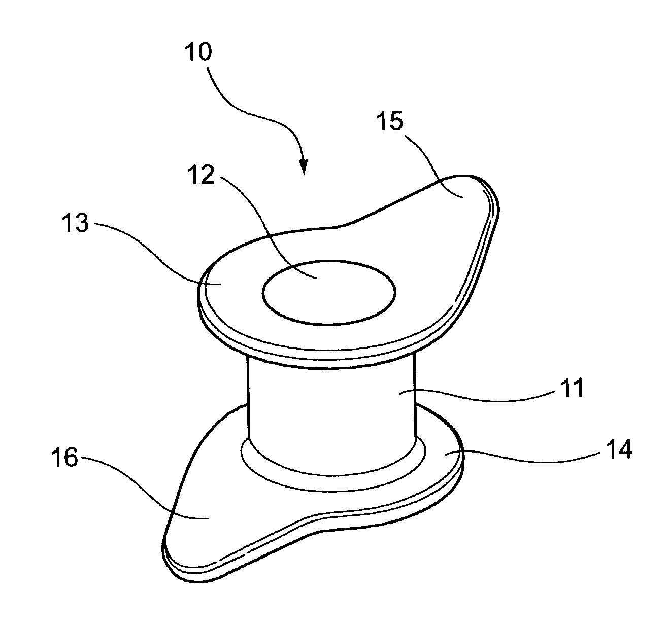
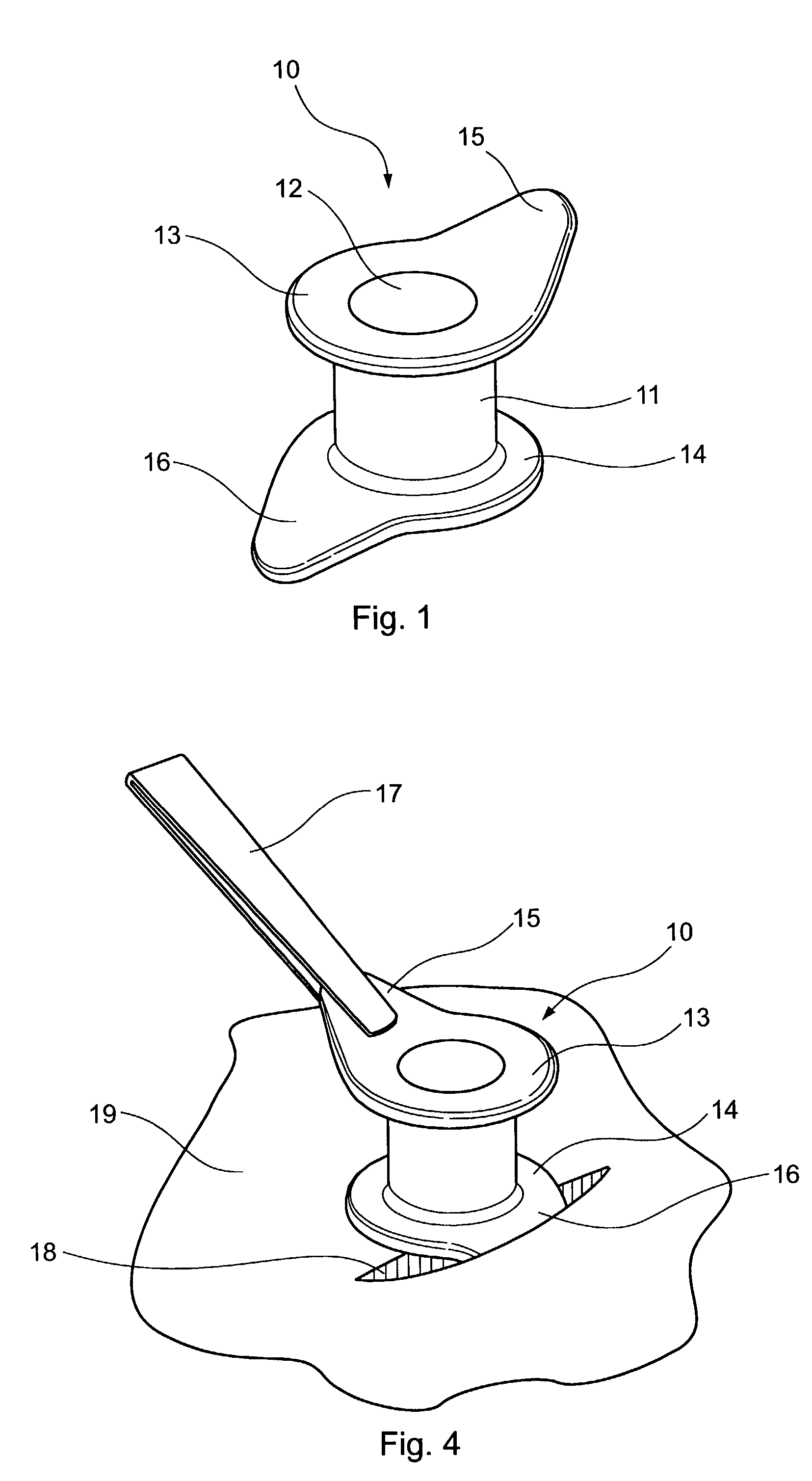
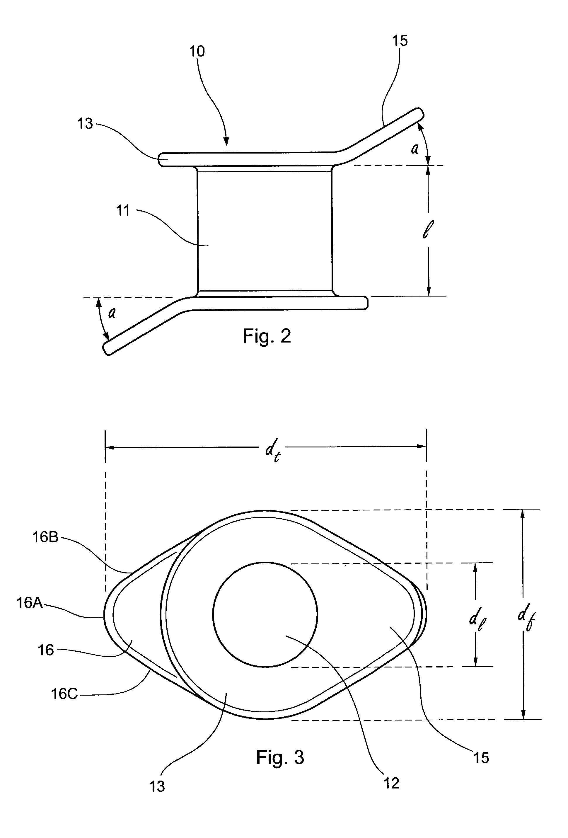
[0016]Each tab preferably is of “blunt arrowhead” shape, comprising a pair of substantially straight edges angled to each other and tangential to its associated flange, and a nose portion with an arcuate edge extending between the substantially straight edges. This shape facilitates insertion of the tab through the incision in the tympanic membrane.
[0018]The incision may have an initial length shorter than the diameter of the flange associated with the other tab. As the other tab is pushed into the membrane, it stretches or widens the incision just enough to accommodate the passage of the tab and its associated flange therethrough, thereby resulting in a snug fit for the ventilation tube in the membrane.

Problems solved by technology

This simple incision in the tympanic membrane may provide temporary relief, but incisions of the eardrum normally self-heal within a relatively short time.
As the ventilation tube is extremely small, typically less than a few millimetres in diameter, and as the tympanic membrane is so delicate, the surgeon must exercise considerable skill and dexterity in the operation.
The surgeon must therefore manoeuvre the grasping forceps to angle the ventilation tube, increasing the difficulty of the operation.
The ventilation tubes of U.S. Pat. No. 5,178,623 may permit the incision and insertion steps to be performed by the same instrumentation, namely the ventilation tube itself, but the provision of a cutting edge on the ventilation tube introduces added risk.
As a myringotomy knife, the ventilation tube, when grasped with forceps by the surgeon, would not be as stable as a regular myringotomy knife, particularly for very thin and flaccid eardrums and excessively thick eardrums.
The cutting edge would therefore appear to be less useful to a surgeon, and possibly more traumatic if the cutting edge inadvertently scratches the skin of the external canal of the ear and / or the drum and medial wall lining of the middle ear, resulting in bleeding and unnecessary injury.
Thus, rather than facilitating the insertion of the ventilation tube, the provision of the cutting edge on the tube requires greater skill and dexterity by the ear surgeon.
The ventilation tube of U.S. Pat. No. 5,207,685 also poses the risk of trauma from its sharp cutting edge.
The ventilation tube is considered unnecessarily complicated and difficult for surgeons and theatre nurses to use.
A significant disadvantage of the ventilation tubes of U.S. Pat. Nos. 5,178,623 and 5,207,685, as well as the ventilation tubes of the other patents identified above, is that they are designed for use in one orientation only.
U.S. design Pat. No. D371606 shows an ear ventilation tube which appears to be reversible, but the tabs of the illustrated ventilation tube are small and therefore difficult to grasp.
The grommet will not slide smoothly to widen the preformed incision resulting possibly in excessive force, a sudden give or tear in the eardrum and the resulting hole possibly being too big to hold the grommet within its space.
Moreover, the tabs are orientated parallel to the longitudinal axis of the tube, and hence the tube is not held at the desired orientation by the grasping forceps.

Method used


Image

  • Ventilation tube for a middle ear
  • Ventilation tube for a middle ear
  • Ventilation tube for a middle ear

Examples


Embodiment Construction

[0024]As shown in FIGS. 1 to 3, a tympanic ventilation tube 10, also known as a grommet, is in the form of a tubular member 11 having a bore 12 therethrough defining a lumen. In use, the ventilation tube 10 is inserted in an incision in a tympanic membrane or eardrum so that the lumen 12 provides a duct or channel for draining fluid from the middle ear and / or ventilating the middle ear space via the external auditory canal.

[0025]The tubular member 11 is provided with generally circular flanges 13, 14 at its opposite ends, each flange being orientated substantially perpendicularly to the axis of the tubular member 11. The flanges 13, 14 serve to retain the ventilation tube in the tympanic membrane. More particularly, by orientating the flanges 13, 14 perpendicularly to the axis of the tubular member 11, they provide greater resistance to the tendency of the eardrum to dislodge the ventilation tube therefrom as the incision heals.

[0026]Each flange 13, 14 has an integrally-formed exten...


PUM


Abstract

A ventilation tube has a tubular member with generally circular flanges at opposite ends. Each flange has a respective tab that is angled obliquely to the axis of the tubular member. The tabs are diametrically opposite, and angled in opposite senses. Each tab has straight non-cutting edges tangential to its associated flange, and an arcuate nose portion. Each flange (may be used either for grasping the ventilation tube, or for insertion into an incision in a tympanic membrane, thereby permitting the ventilation tube to be used reversibly.

Description

[0001]This invention relates to an improved ventilation tube for a middle ear. In particular, the invention is directed to a ventilation tube which can be inserted into a patient's tympanic membrane (eardrum) in either of two opposite orientations.BACKGROUND ART[0002]Many persons, particularly children, suffer from accumulation of fluid in the middle ear. In a surgical operation, known as a myringotomy or tympanostomy, an incision is made in the tympanic membrane or eardrum to ventilate the middle ear and / or drain the fluid. This simple incision in the tympanic membrane may provide temporary relief, but incisions of the eardrum normally self-heal within a relatively short time. For ventilation / drainage for longer periods, after myringotomy the surgeon inserts a ventilation tube or “grommet” through the incision, thereby providing a vent which equalises the pressure on either side of the eardrum, and allows fluid to be drained from the middle ear. The eardrum soon heals around the wa...

Claims


Application Information

Patent Timeline
IPC IPC(8): A61F2/18A61F11/00A61M31/00
CPCA61F11/002A61F11/202
Inventor PERRY, CHRISTOPHER FRANCIS
Owner PERRY MICROTUBE
Learn More