Eureka AIR delivers breakthrough ideas for toughest innovation challenges, trusted by R&D personnel around the world.

Load detecting device

a detection device and load technology, applied in the direction of optical radiation measurement, force measurement by measuring optical property variation, instruments, etc., can solve the problems of small load per unit area (unit length), low sensitivity, and large device on the whol

Inactive Publication Date: 2006-08-29
ASMO CO LTD
View PDF6 Cites 5 Cited by
  • Summary
  • Abstract
  • Description
  • Claims
  • Application Information

AI Technical Summary

Benefits of technology

[0013]In view of the aforementioned, the present invention provides a load detecting device which is compact and has good sensitivity.

Problems solved by technology

However, in the above-described conventional optical fiber sensors, in a case in which a load (pressing force) is received substantially uniformly over a wide range in the longitudinal direction, the load per unit area (unit length) is small, and therefore, there is the problem that the sensitivity is low.
Therefore, the device becomes large on the whole.
Thus, the number of parts or the amount of material which is used increase, and there is the problem that the cost increases.

Method used


Image

  • Load detecting device
  • Load detecting device
  • Load detecting device

Examples


second embodiment

[0115]Next, a pressure-sensitive sensor 50 serving as a load detecting device relating to a second embodiment of the present invention will be described on the basis of FIGS. 5 through 8A and 8B. Note that parts and portions which are basically the same as those of the above-described first embodiment are denoted by the same reference numerals as in the first embodiment, and description thereof is omitted.

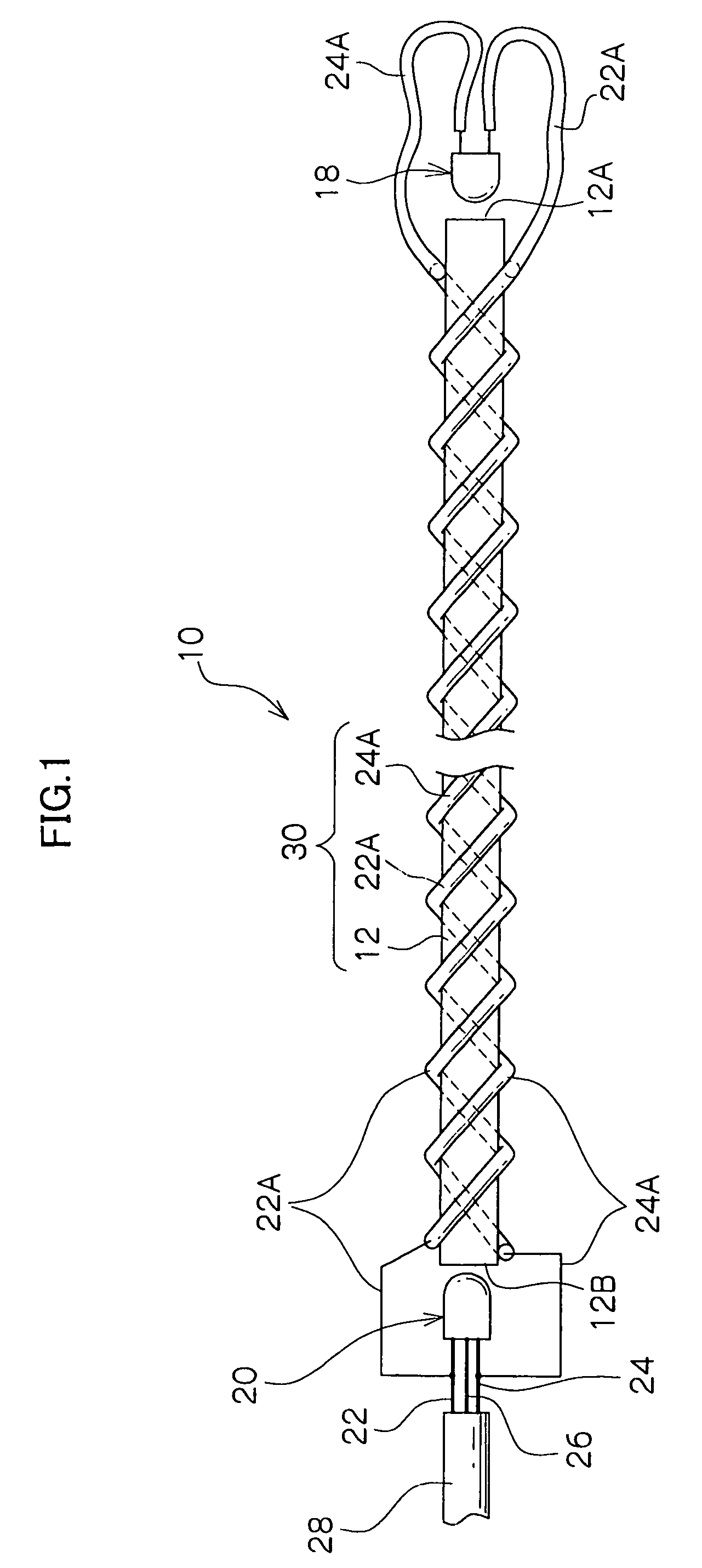
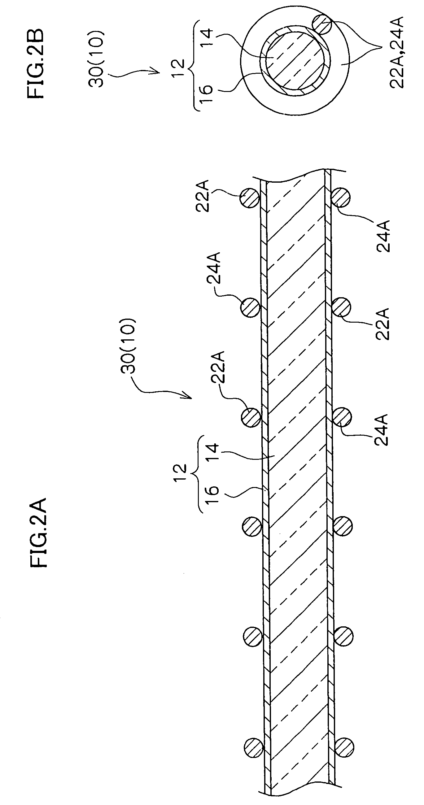
[0116]The schematic overall structure of the pressure-sensitive sensor 50 is shown in sectional view in FIG. 5. The pressure-sensitive sensor 50 is shown in side view in FIG. 6. As shown in these figures, the pressure-sensitive sensor 50 has the optical fiber 12 around which the power source wire 22A for light-emission and the ground wire 24A for light-emission are wound in spiral forms, the light-emitting element 18, and the light-receiving element 20. The pressure-sensitive sensor 50 is electrically structured exactly the same as the pressure-sensitive sensor 10 (see FIG. 3), and...


PUM

PropertyMeasurementUnit
diameteraaaaaaaaaa
lengthaaaaaaaaaa
external forceaaaaaaaaaa

Abstract

A pressure-sensitive sensor which is a load detecting device of the present invention is structured to include: an optical fiber of a predetermined length; a light-emitting element, disposed at a longitudinal direction one end side of the optical fiber, for emitting light and making the light incident from one end of the optical fiber; a light-receiving element, disposed at a longitudinal direction other end side of the optical fiber, for receiving light which has passed through the optical fiber and outputting a signal corresponding to an amount of received light; and a power source wire for light-emission and a ground wire for light-emission which are wound around an outer periphery of the optical fiber, and are formed in spiral forms along the outer periphery, and are connected to the light-emitting element. The power source wire for light-emission, which forms a spiral form at the outer periphery of the optical fiber, functions as a pressure element and improves sensitivity of the pressure-sensitive sensor.

Description

CROSS-REFERENCE TO RELATED APPLICATION[0001]This application claims priority under 35 USC 119 from Japanese Patent Application No. 2003-171980, the disclosure of which is incorporated by reference herein.BACKGROUND OF THE INVENTION[0002]1. Field of the Invention[0003]The present invention relates to a load detecting device using an optical fiber.[0004]2. Description of the Related Art[0005]Vehicles such as automobiles and the like are equipped with catching detecting sensors for detecting that a foreign object is caught (trapped), for example, between the window frame and a side window glass which is driven by a power window device, or between the vehicle body and a motor-operated sliding door or back door. Pressure-sensitive sensors, which detect the pressing force which accompanies the catching of a foreign object (the reaction force received from the foreign object), are used as the catching sensors.[0006]It has been thought to use an optical fiber sensor as the pressure-sensitiv...

Claims


Application Information

Patent Timeline
Patent Type & Authority Patents(United States)
IPC IPC(8): H01J5/16E05F15/00G01L1/24
CPCG01L1/243E05F15/43E05F2015/434E05F15/42
Inventor ISHIHARA, HIDENORI
Owner ASMO CO LTD
Why Eureka
Eureka Blog
Learn More