Liquid crystal display device comprising pixel and common electrodes inclined in first and second directions to form a zigzag shape which is symmetrical relative to alignment direction of liquid crystal

Inactive Publication Date: 2006-08-29
LG DISPLAY CO LTD
View PDF8 Cites 14 Cited by
  • Summary
  • Abstract
  • Description
  • Claims
  • Application Information

AI Technical Summary

Benefits of technology

[0019]Thus, in the liquid crystal display device using the structure of the present invention, the combination of the alignment film and the liquid crystal is freely selected without being limited by the pretilt angle. In other words, the method of the present invention can solve the inherent problems in the conventional transverse electric field system such as an inferior residual image and a response speed.
[0020]Further in the present invention, since the pretilt angle will not adversely affect the performance even when the combination of the alignment film and liquid crystal of the conventional transverse electric field system is used, the production line for the vertical electric field system needs not be changed, and thus the productivity will not decrease.
[0021]By using the above described methods in the first to fifth embodiments, it has become possible to separate the rotation motions of the liquid crystal molecule into two direct

Problems solved by technology

When an alignment film and liquid crystal with one (1) degree of pretilt are used in a liquid crystal display of the vertical electric field system, a reverse tilt domain will be created by the electric field of video signal lines and pixel electrodes, resulting i

Method used


Image

  • Liquid crystal display device comprising pixel and common electrodes inclined in first and second directions to form a zigzag shape which is symmetrical relative to alignment direction of liquid crystal
  • Liquid crystal display device comprising pixel and common electrodes inclined in first and second directions to form a zigzag shape which is symmetrical relative to alignment direction of liquid crystal
  • Liquid crystal display device comprising pixel and common electrodes inclined in first and second directions to form a zigzag shape which is symmetrical relative to alignment direction of liquid crystal

Examples


embodiment 1

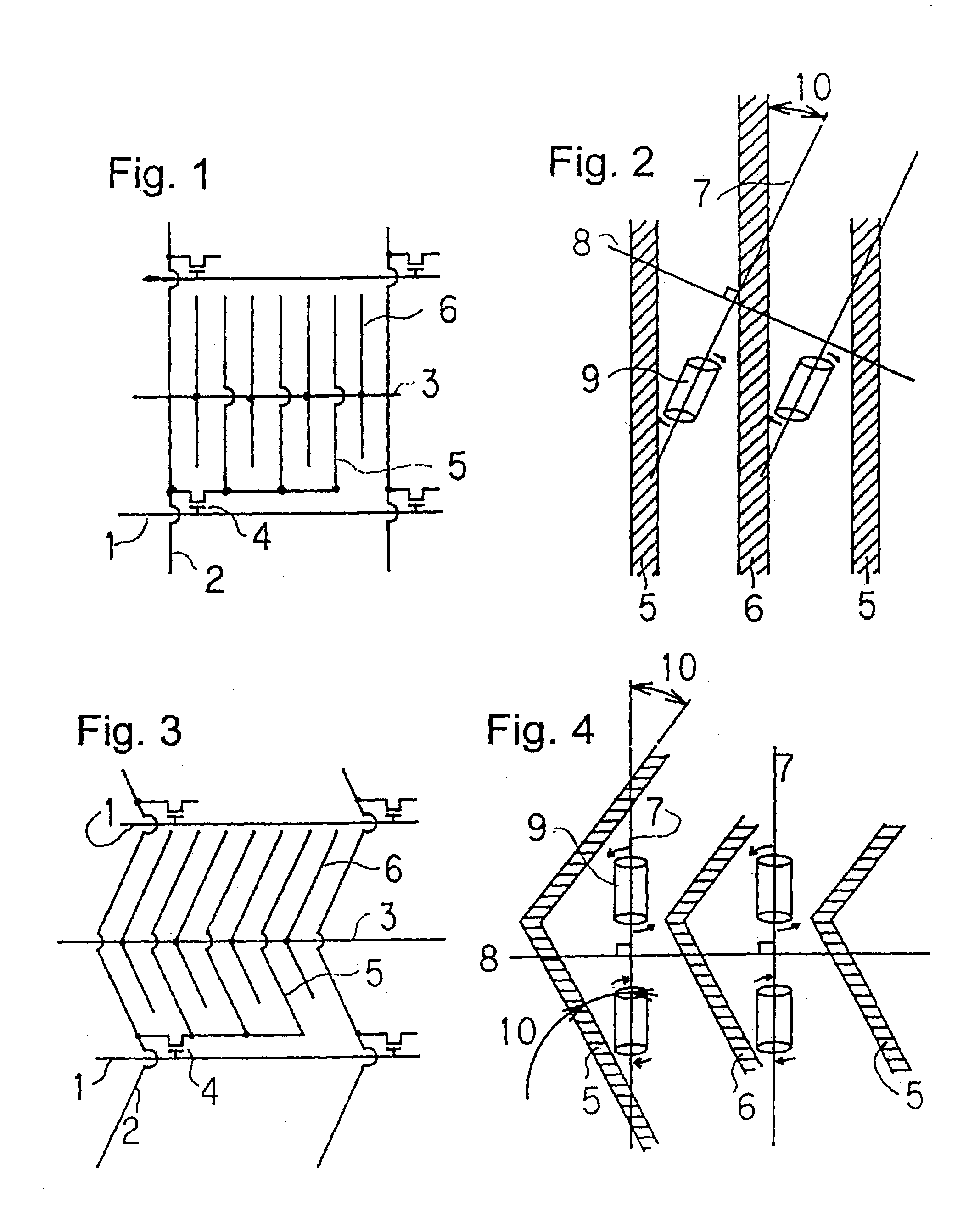
[0038]FIGS. 3 and 4 are plan views of a unit pixel showing a basic operational principle of the first embodiment of the present invention. In this example, dielectric anisotropy of the liquid crystal molecule is positive. In FIG. 3, numeral 1 designates a scanning line, numeral 2 is a video signal line, numeral 3 is a common line, numeral 4 is a thin film transistor (TFT), numeral 5 is a pixel electrode (liquid crystal drive electrode), and numeral 6 is a common electrode.

[0039]In FIG. 4, numeral 5 designates a pixel electrode (liquid crystal drive electrode), numeral 6 is a common electrode, numeral 7 is a alignment direction of the liquid crystal molecules as well as a polarization axis of a polarizing plate, numeral 8 is a polarization axis of the other polarizing plate, numeral 9 is a liquid crystal molecule of a positive dielectric anisotropy under zero electric field (P-type liquid crystal molecule), and numeral 10 is an angle that is formed by crossing the alignment direction...

embodiment 2

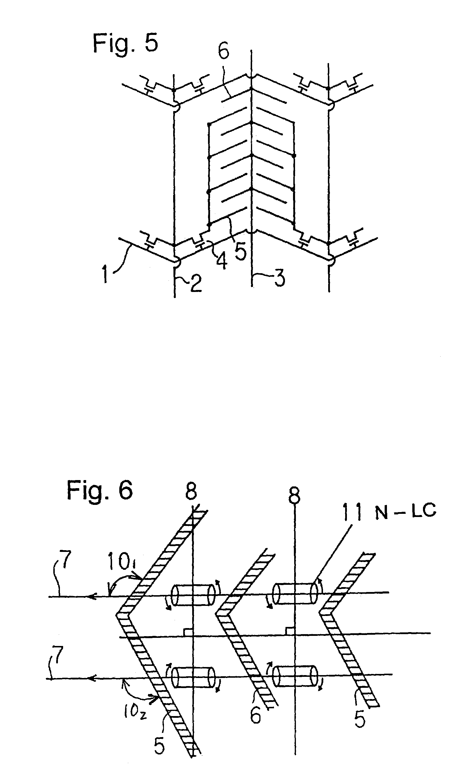
[0041]FIGS. 4 and 5 are plan views of a unit pixel showing a basic operational principle of the second embodiment of the present invention. In this example, dielectric anisotropy of the liquid crystal molecule is positive. As shown in FIGS. 4 and 5, the scanning line 1 and the pixel electrodes 5 and the common electrodes 6 are so configured as to be bent relative to the alignment direction of the P-type liquid crystal. The bent angle 10 can be selected to be an angle with the best display performance as long as the angle is within the range from ±1 to ±30 degrees. As shown in FIG. 7, there is no limit in the number of bent of the electrodes.

embodiment 3

[Embodiment 3]

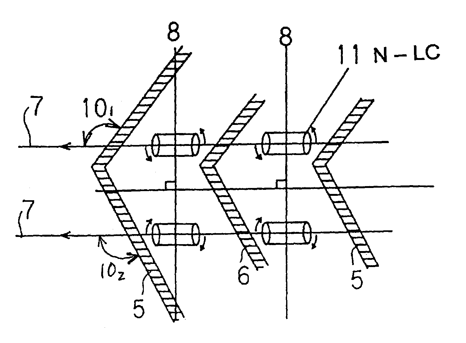
[0042]FIGS. 3 and 6 are plan views of a unit pixel showing a basic operational principle of the third embodiment of the present invention. In this example, dielectric anisotropy of the liquid crystal molecule is negative. In FIG. 6, numeral 5 designates a pixel electrode (liquid crystal drive electrode), numeral 6 is a common electrode, numeral 7 is an alignment direction of the liquid crystal molecule as well as a polarization axis of a polarizing plate, numeral 8 is a polarization axis of the other polarizing plate, numeral 10 is an angle that is formed by crossing the alignment direction of the N-type liquid crystal molecule and the pixel electrode, and numeral 11 is a liquid crystal molecule of a negative dielectric anisotropy under zero electric field (N-type liquid crystal molecule). As shown in FIGS. 3 and 6, the video signal line 2 and the pixel electrodes 5 and the common electrodes 6 are so configured as to be bent relative to the alignment direction of the N...


PUM


Abstract

An active matrix type liquid crystal display device where display pixels are constituted on a substrate by scanning signal lines, video signal lines, pixel electrodes, common electrodes and active elements in order to obtain an image having good visual field angle characteristics and a high display quality with less residual image. The substrate is opposed to another substrate having a color filter forming a liquid crystal alignment film, and the liquid crystal layer is held by the two substrates. The electrodes and the active elements are so constituted that an electric field can be applied to the liquid crystal layer substantially in parallel with the substrate. The video signal lines, the common electrodes and the pixel electrodes are bent within a range of 60 to 120 degrees relative to the direction of liquid crystal alignment.

Description

[0001]This is a continuation-in-part of U.S. application Ser. No. 09 / 610,815 filed Jul. 6, 2000 now abandoned which is a continuation of U.S. application Ser. No. 09 / 142,448, filed Sep. 3, 1998 now U.S. Pat. No. 6,288,763 which is a 371 of PCT / JP01304 filed Apr. 15, 1997 which claims the benefit of Japanese Patent application No. 8-158741 filed Apr. 16, 1996.FIELD OF THE INVENTION[0002]This invention relates to an active matrix type liquid crystal display device which has improved visual field angle characteristics and high display quality with less residual image by utilizing bent electrodes.BACKGROUND OF THE INVENTION[0003]A conventional technology for applying an electric field to a liquid crystal composition layer is proposed, for instance, in Japanese Laid-Open Patent Publication No. 7-36058 and No. 7-159786 in which an electric field is applied to a pair of comb like electrodes formed on a substrate of an active matrix type liquid crystal display device. Heretofore, a display ...

Claims


Application Information

Patent Timeline
IPC IPC(8): G02F1/1343G02F1/1337
CPCG02F1/134363G02F1/1337
Inventor HIROTA, NAOTO
Owner LG DISPLAY CO LTD
Why Eureka
Try Eureka