Spin polarization enhancement artificial magnet

a technology of artificial magnets and spin polarization, applied in the field of spin-dependent scattering, can solve the problems of loss, limiting factor in many cip sensors, and achieve the effect of enhancing the spin polarization of current passing

Inactive Publication Date: 2006-08-29
SEAGATE TECH LLC
View PDF23 Cites 15 Cited by
  • Summary
  • Abstract
  • Description
  • Claims
  • Application Information

AI Technical Summary

Benefits of technology

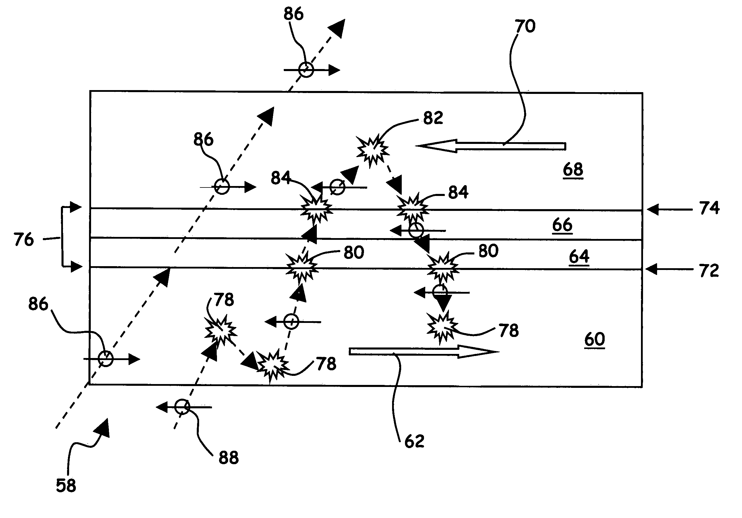
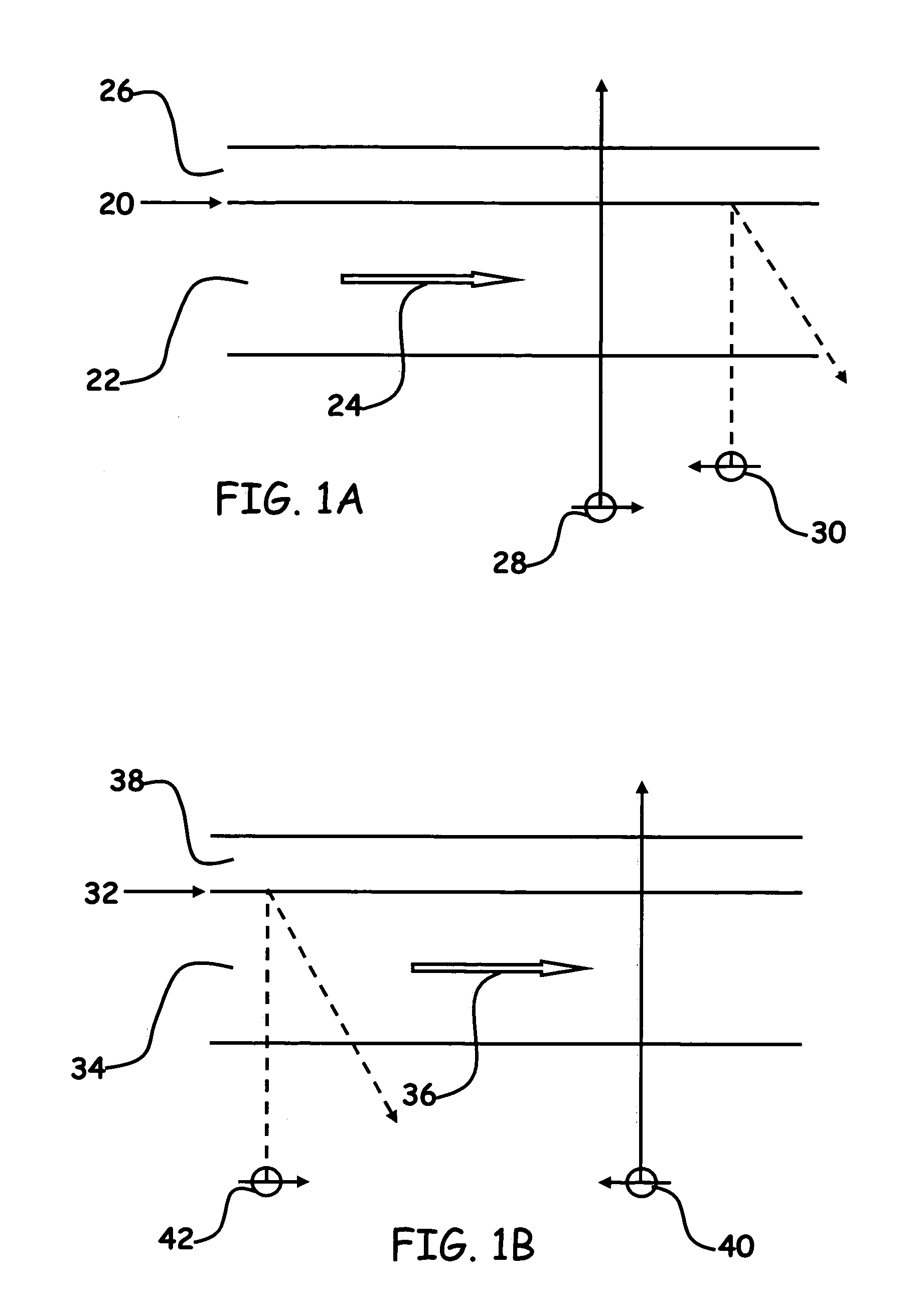
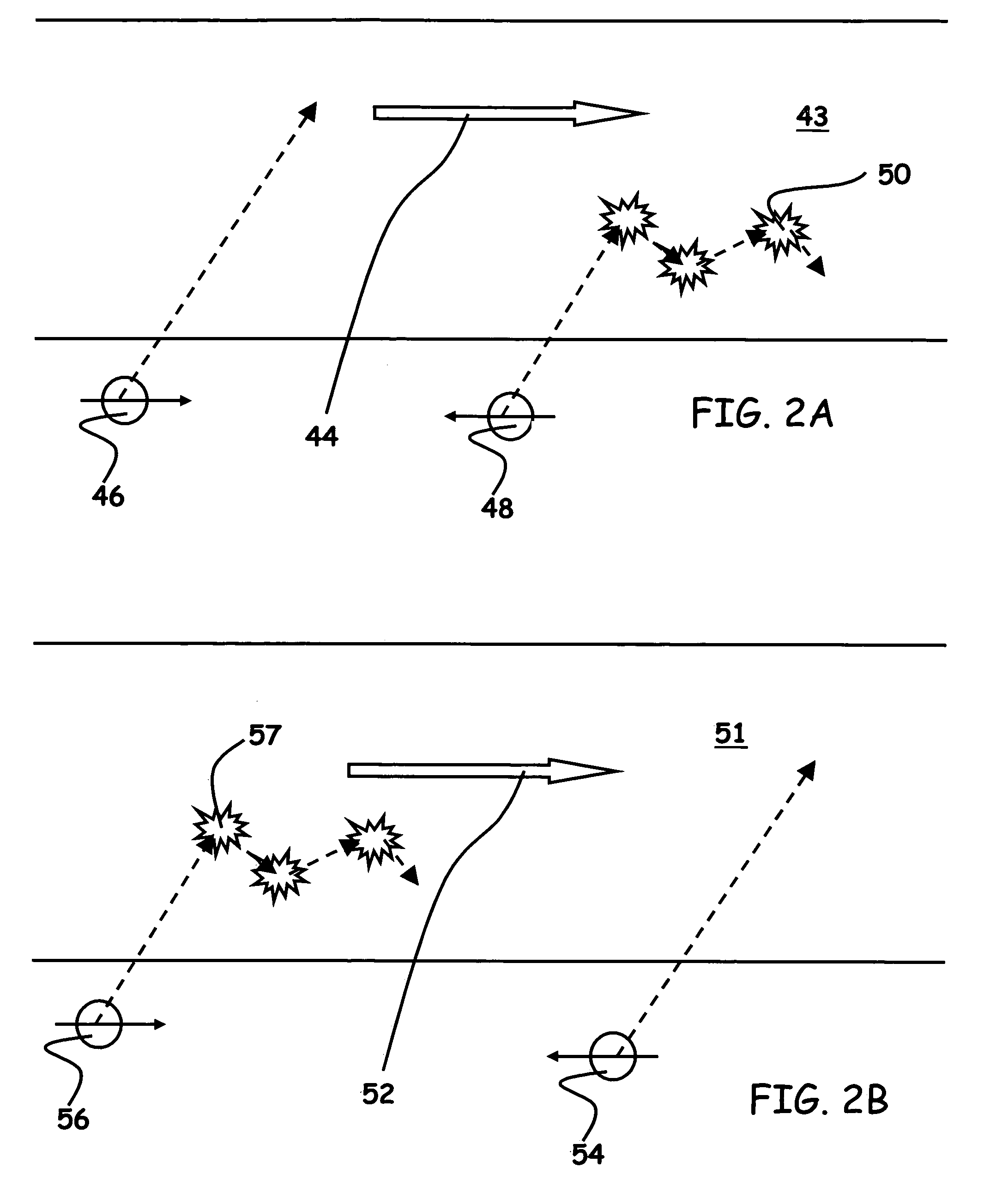
[0010]A basic functional unit of the SPEA magnet consists of two ferromagnetic layers separated by two spacer layers. Each spacer is selected to engineer an interface with the adjacent ferromagnetic layer with either positive or inverse spin symmetry. Preferably, both positive and inverse spin symmetry interfaces are formed within the SPEA magnet. Antiferromagnetic arrangement of adjacent ferromagnetic layers coordinates the different spin symmetries such that a single spin state is selected, resulting in enhanced spin polarization of current passing through the SPEA magnet. The antiferromagnetic arrangement also provides additional stabilization to the SPEA magnet.

Problems solved by technology

A limiting factor in many of CIP sensors is the decrease in amplitude due to loss of free layer area as the reader width decreases.

Method used


Image

  • Spin polarization enhancement artificial magnet
  • Spin polarization enhancement artificial magnet
  • Spin polarization enhancement artificial magnet

Examples


embodiment 90

[0058]FIG. 5A illustrates a first alternative embodiment 90 of the SPEA magnet. SPEA magnet 90 comprises: first magnetic layer 92, first spacer layer 94, second spacer layer 96, second magnetic layer 98, third spacer layer 100, fourth spacer layer 102, and third magnetic layer 104. SPEA magnet 90 also comprises: first interface 106, second interface 108, third interface 110, and fourth interface 112.

[0059]First magnetic layer 92 contacts first spacer layer 94 thereby forming first interface 106. Similarly, second magnetic layer 98 contacts second spacer layer 96, thereby forming second interface 108. First spacer layer 94 and second spacer layer 96 may also be described as a bi-layer spacer. Second magnetic layer 98 additionally contacts third spacer layer 100 thereby forming third interface 110. Third magnetic layer 104 contacts fourth spacer layer 102 thereby forming fourth interface 112. Third spacer layer 100 and fourth spacer layer 102 may also be described as a bi-layer spacer...

fourth embodiment

[0085]FIG. 10 is an SPEA magnet. SPEA magnet 184 includes an alternative arrangement of interface types: inverse—positive—inverse groupings of interfaces. Each group may include either one or two interfaces.

[0086]SPEA magnet 184 comprises: bottom spacer 186; first interface 188; first magnetic layer 190 with magnetization 191; second interface 192; first bi-layer spacer 194 formed of first layer 196 and second layer 198; third interface 200; second magnetic layer 202 with magnetization 203; fourth interface 204; second bi-layer spacer 206 formed of first layer 208 and a second layer 210; fifth interface 212; third magnetic layer 214 with magnetization 215; sixth interface 216; and top spacer 218.

[0087]First interface 188 is formed at the bottom of first magnetic layer 190 where it contacts bottom spacer 186. Second interface 192 is formed at the top of first magnetic layer 190 where it contacts first layer 196 of first bi-layer spacer 194. Third interface 200 is formed at the bottom...


PUM

PropertyMeasurementUnit
magnetizationaaaaaaaaaa
magneticaaaaaaaaaa
non-magneticaaaaaaaaaa

Abstract

A spin polarization enhancement artificial (SPEA) magnet comprises combinations of positive spin asymmetry interfaces and inverse spin asymmetry interfaces arranged antiferromagnetically such that current passed through the SPEA magnet has enhanced spin polarization. The SPEA magnet additionally may combine bulk material properties of electron scattering to either supplement or replace the interfacial spin differentiation. A basic functional unit of the SPEA magnet includes two ferromagnetic layers separated by two spacer layers. Each spacer forms an interface such that adjacent ferromagnetic layers produce different spin symmetry. Antiferromagnetic arrangement of adjacent ferromagnetic layers coordinates the different spin symmetries such that a single spin state is selected and also provides additional stabilization to the SPEA magnet.

Description

BACKGROUND OF THE INVENTION[0001]The present invention relates generally to the field of spin-dependent scattering of electrons to spin polarize current. In particular, the present invention relates to an artificial magnet with spin polarization enhancement for use in magnetoresistive devices.[0002]Magnetoresistive (MR) devices generally operate by responding to changes in local magnetic flux. For example in a magnetic data storage and retrieval system, a magnetic recording head typically includes a reader portion having a magnetoresistive (MR) sensor for retrieving magnetically encoded information stored on a magnetic disc. Magnetic flux from the surface of the disc causes rotation of the magnetization vector of a sensing layer or layers of the MR sensor, which in turn causes a change in electrical resistivity of the MR sensor. The sensing layers are often called free layers, since the magnetization vectors of the sensing layers are free to rotate in response to external magnetic f...

Claims


Application Information

Patent Timeline
Patent Type & Authority Patents(United States)
IPC IPC(8): G11B5/39G11B5/127G11B5/33
CPCG11B5/39B82Y10/00
Inventor YI, GELAMBERTON, ROBERT W.MURDOCH, SUSAN JANE TARAMCLAUGHLIN, THOMAS K.O'KANE, WILLIAM J.
Owner SEAGATE TECH LLC
Why Eureka
Try Eureka