Multilayer capacitor

a multi-layer capacitor and capacitor technology, applied in the field of multi-layer capacitors, can solve the problems of reducing the equivalent series resistance of the multi-layer capacitor in excess, and the bulky multi-layer body, and achieve the effect of easy regulation of the equivalent series resistan

Active Publication Date: 2006-08-29
TDK CORPARATION
View PDF8 Cites 16 Cited by
  • Summary
  • Abstract
  • Description
  • Claims
  • Application Information

AI Technical Summary

Benefits of technology

[0008]It is an object of the present invention to provide a multilayer capacitor which can easily regulate its equivalent series resistance.
[0010]Therefore, the inventors diligently conducted studies about multilayer capacitors which can satisfy both of the demands for increasing the capacitance and equivalent series resistance, and have noticed that the equivalent series resistance can be made greater when lead electrodes are elongated even if the number of laminated dielectric layers and inner electrode layers is the same. However, simply elongating the lead electrode makes the multilayer body bulky. As a consequence, the inventors have found a new fact that, when an electrode portion forming a capacitance component is provided with a portion also functioning as a lead electrode, the portion equivalent of a lead electrode becomes substantially long and can restrain the equivalent series resistance from decreasing in excess. The inventors have also found a new fact that the equivalent series resistance can be adjusted to a desirable value depending on the length of the above-mentioned portion also functioning as a lead electrode.
[0014]In each of the multilayer capacitors in accordance with these aspects of the present invention, the portion positioned between a pair of slits in each of the first and second capacitor electrodes functions as an electrode portion forming a capacitance component and also as a lead electrode. Therefore, portions corresponding to lead electrodes in the first and second inner electrode layers are substantially elongated. As a consequence, these multilayer capacitors can increase the equivalent series resistance while securing the capacitance. By providing first and second capacitor electrodes with slits extending from peripheries corresponding to first and second lead electrodes, respectively, these multilayer capacitors regulate the equivalent series resistance. Therefore, these multilayer capacitors can regulate the equivalent series resistance easily.
[0015]Preferably, at least one of the respective portions of the first and second capacitor electrodes positioned between the pairs of slits has a meandering or crank-shaped form. In this case, the portion corresponding to a lead electrode in at least one of the first and second inner electrode layers becomes further longer. Consequently, the value of equivalent series resistance can be made further greater.
[0020]Preferably, an equivalent series resistance is set to a desirable value by regulating a length of the slits. In this case, the length of the portion positioned between a pair of slits is regulated, whereby a multilayer capacitor having a desirable value of equivalent series resistance can be obtained easily.
[0021]The present invention can provide a multilayer capacitor which can easily regulate the equivalent series resistance.

Problems solved by technology

However, the multilayer capacitor disclosed in Japanese Patent Application Laid-Open Nos. 2004-140211 does not take the equivalent series resistance into consideration.
Therefore, there is a fear of this multilayer capacitor lowering its equivalent series resistance in excess.
However, simply elongating the lead electrode makes the multilayer body bulky.

Method used


Image

  • Multilayer capacitor
  • Multilayer capacitor
  • Multilayer capacitor

Examples


first embodiment

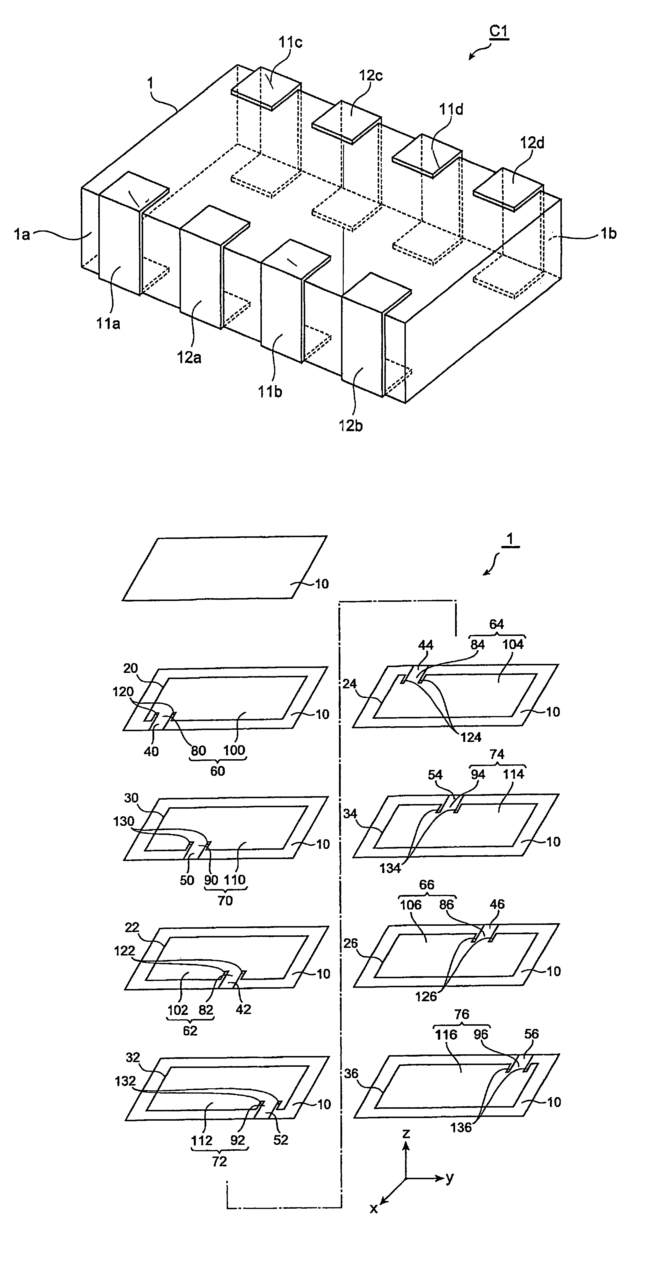
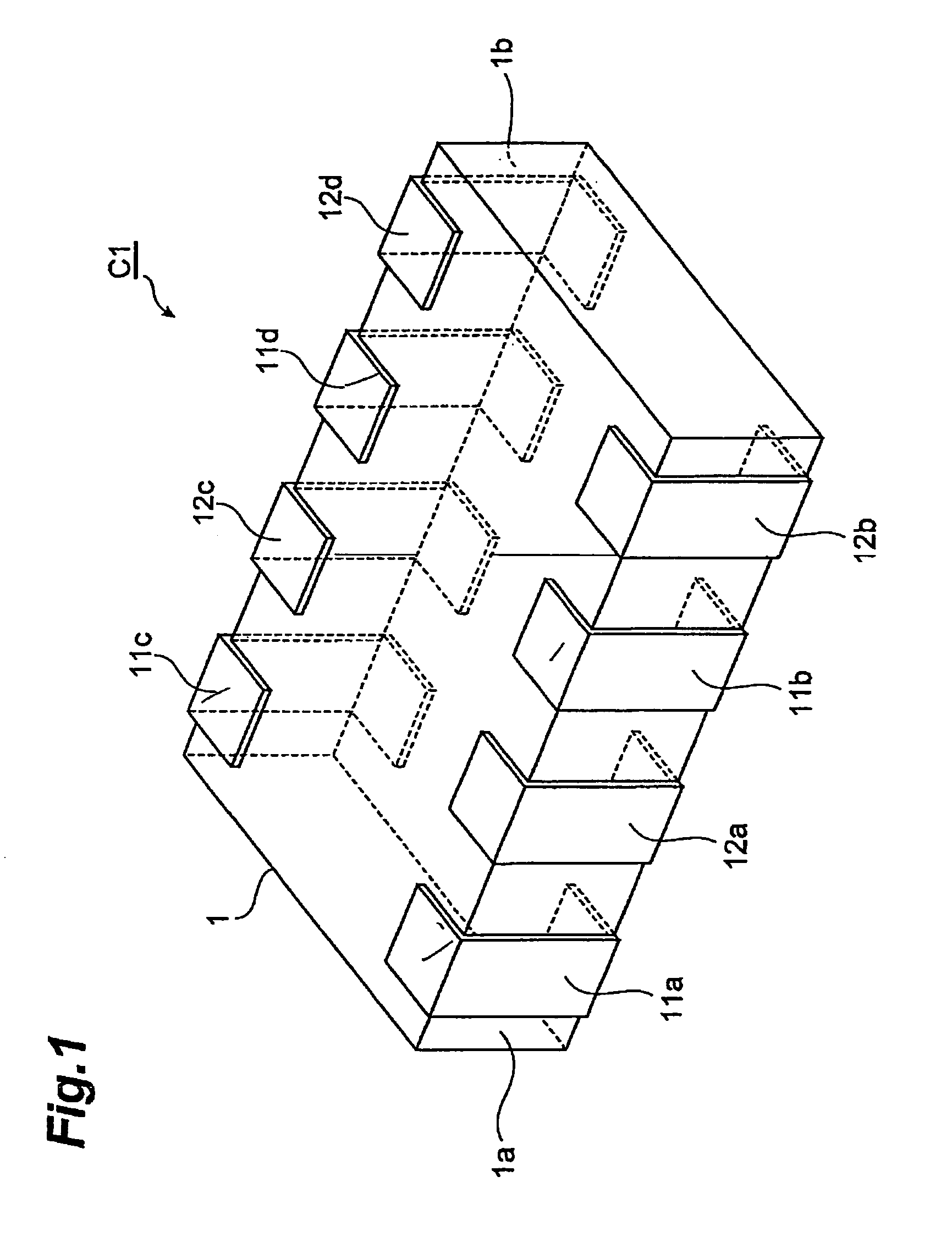
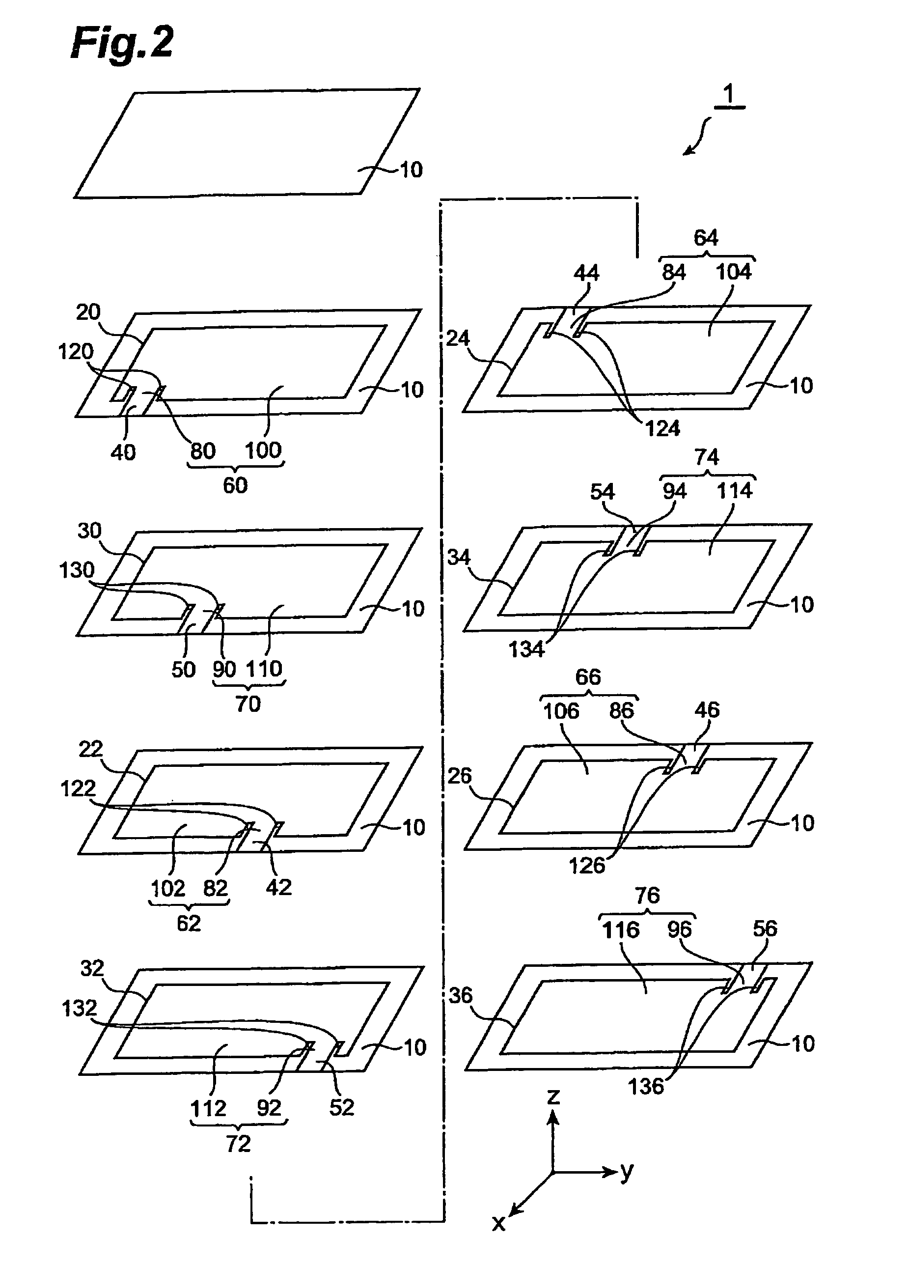
[0042]With reference to FIGS. 1 and 2, the structure of the multilayer capacitor C1 in accordance with a first embodiment will be explained. FIG. 1 is a perspective view of the multilayer capacitor in accordance with the first embodiment. FIG. 2 is an exploded perspective view of the multilayer body included in the multilayer capacitor in accordance with the first embodiment.

[0043]As shown in FIG. 1, the multilayer capacitor C1 comprises a multilayer body 1, and first and second terminal electrodes 11a to 11d, 12a to 12d which are formed on the multilayer body 1.

[0044]The first and second terminal electrodes 11a to 11d, 12a to 12d are provided four by four, and are electrically insulated from each other. Among the four first terminal electrodes 11a, 11b, 11c, 11d, two first terminal electrodes 11a and 11b are positioned on a side face 1a of the multilayer body 1, whereas the remaining two first terminal electrodes 11c and 11d are positioned on a side face 1b of the multilayer body 1...

second embodiment

[0058]The structure of the multilayer capacitor in accordance with a second embodiment will be explained with reference to FIG. 3. The multilayer capacitor in accordance with the second embodiment differs from the multilayer capacitor in accordance with the first embodiment in terms of the form of capacitor lead electrodes. FIG. 3 is an exploded perspective view of the multilayer body 1 included in the multilayer capacitor in accordance with the second embodiment.

[0059]In the multilayer body 1, as shown in FIG. 3, each of first and second capacitor lead electrodes 80 to 86, 90 to 96 has a meandering form. Each of first and second lead electrodes 40 to 46, 50 to 56 continuous with corresponding one of the first and second capacitor lead electrodes 80 to 86, 90 to 96 also has a meandering form.

[0060]In the multilayer capacitor in accordance with this embodiment, as in the foregoing, portions substantially corresponding to lead electrodes for the first and second inner electrode layers...

third embodiment

[0065]With reference to FIG. 5, the structure of the multilayer capacitor in accordance with a third embodiment will be explained. The multilayer capacitor in accordance with the third embodiment differs from the multilayer capacitor in accordance with the first embodiment in that capacitor lead electrodes or lead electrodes have openings. FIG. 5 is an exploded perspective view of the multilayer body 1 included in the multilayer capacitor in accordance with the third embodiment.

[0066]In the multilayer body 1, as shown in FIG. 5, first and second lead electrodes 40 to 46, 50 to 56 and first and second capacitor lead electrodes 80 to 86, 90 to 96 have circular openings 140, 142, 144, 146, 150, 152, 154, 156. The openings 140 to 146 are formed by respective rows of three circular apertures aligning in the X-axis direction in portions where the first lead electrodes 40 to 46 are continuous with their corresponding first capacitor lead electrodes 80 to 86. The openings 150 to 156 are for...


PUM


Abstract

A multilayer capacitor comprises a multilayer body and a plurality of terminal electrodes formed on the multilayer body. The plurality of terminal electrodes include first and second terminal electrodes. The multilayer body is constructed by alternately laminating a plurality of dielectric layers and first and second inner electrode layers. The first inner electrode layer includes a first lead electrode electrically connected to the first terminal electrode and a first capacitor electrode forming a capacitance component. The portion positioned between a pair of slits provided in the first capacitor electrode is continuous with the first lead electrode. The second inner electrode layer includes a second lead electrode electrically connected to the second terminal electrode and a second capacitor electrode forming a capacitance component. The portion positioned between a pair of slits provided in the second capacitor electrode is continuous with the second lead electrode.

Description

BACKGROUND OF THE INVENTION[0001]1. Field of the Invention[0002]The present invention relates to a multilayer capacitor.[0003]2. Related Background Art[0004]Known as this kind of multilayer capacitor is one comprising a multilayer body in which a plurality of dielectric layers and a plurality of inner electrode layers are alternately laminated, and a plurality of terminal electrodes formed on the multilayer body (see, for example, Japanese Patent Application Laid-Open No. 2004-140211).[0005]Power supplies for central processing units (CPUs) mounted in digital electronic devices have been increasing their load current while lowering their voltage. Therefore, it has become quite difficult to suppress the fluctuation in power supply voltage under a tolerable level in response to a drastic change in load current. Hence, a multilayer capacitor known as decoupling capacitor has come into connection with a power supply. At the time when the load current fluctuates transiently, the multilay...

Claims


Application Information

Patent Timeline
Patent Type & Authority Patents(United States)
IPC IPC(8): H01G4/005H01G4/06
CPCH01G4/012H01G4/30H01G4/232
Inventor TOGASHI, MASAAKIAHIKO, TAISUKE
Owner TDK CORPARATION
Why Eureka
Try Eureka