Method and apparatus for manufacturing solid electrolytic capacitor

a solid electrolytic capacitor and electrolytic capacitor technology, which is applied in the manufacture of capacitors, electrolytic capacitors, and electrolytic capacitors, etc., can solve the problems of inconvenient powder sintered body method, inability to directly apply method, and inability to use aluminum formation foil method for aluminum formation foil, etc., to achieve high capacitance, reduce the effect of esr and increase the distance of dipping

Active Publication Date: 2010-07-08
RESONAC CORP
View PDF11 Cites 4 Cited by
  • Summary
  • Abstract
  • Description
  • Claims
  • Application Information

AI Technical Summary

Benefits of technology

[0021]The present invention is to provide, in a method for producing a solid electrolytic capacitor by forming a dielectric layer on an anode body comprising a valve-acting metal sintered body having particularly fine pores and forming on the dielectric layer a conductive compound layer (for example, a layer obtained by impregnation of an organic compound solution, an organic compound solution or a conductive polymer dispersion liquid followed by heating), a method for producing a solid electrolytic capacitor, wherein the distance (depth) of dipping is increased with each dipping of a porous body composed of valve-acting metal and the like into an inorganic compound solution, an organic compound solution or a conductive polymer compound dispersion liquid which turns into a conductive compound layer so that the apertures on the surface of the sintered porous body may not be completely closed to thereby makes it possible to form a cathode efficiently by delivering the solution to the depth until a cathode layer is sufficiently formed; and an apparatus to be used for the method (a dipping apparatus of a solution or a dispersion liquid which turns into a cathode compound layer).
[0022]According to the present invention, a cathode layer can be formed efficiently in the anode body comprising a valve-acting metal sintered body having fine pores and, as a result, a solid electrolytic capacitor having high capacitance and low ESR (equivalent series resistance) can be produced.
[0023]Examples of the sintered body used in the present invention include a sintered body having numerous fine pores inside which is obtained by molding and then sintering powder such as tantalum powder, niobium powder, alloy powder mainly comprising tantalum, alloy powder mainly comprising niobium and niobium monoxide powder. In the case of these sintered body, an outgoing lead can be directly connected to the sintered body. Also, in a case where a powdery conductor is molded or sintered after molded, a part of a separately-prepared outgoing lead (or a lead foil) may be molded together with the powder at the time of molding and thus the other part of the outgoing lead (or a lead foil) outside the molded body may be used as outgoing lead of one electrode in the solid electrolytic capacitor element. It is also possible to leave a part of the sintered body without forming a cathode layer thereon to be used as an anode part.
[0024]Specific examples of an inorganic compound solution which turns into a cathode compound layer in the present invention include a solution of various metal salts which can form one member of molybdenum dioxide, tungsten dioxide, zinc dioxide, manganese dioxide and the like.
[0025]Examples of an organic compound solution include an alcohol solution, ketone solution or ester solution of furan, pyrrole, thiophene, aniline or a substituted derivative thereof.
[0026]Examples of a polymer compound dispersion liquid include a dispersion liquid of polyaniline, polyoxyphenylene, polyphenylene sulfide, polythiophene, polyfuran, polypyrrole, polymethylpyrrole, and a substitution derivative and a copolymer thereof. Among these, preferred is a dispersion liquid of polypyrrole, polythiophene and a substitution derivative thereof (e.g., poly(3,4-ethylenedioxythiophene)).

Problems solved by technology

However, in the method the cathode-forming solution penetrates inside the anode body through capillarity using that the anode body made of valve-acting metal is a porous body, and the method cannot be directly applied in the cases where the solution is a low-temperature or high-concentration solution having high viscosity.
However, the penetration depth of the cathode-formation solution to go deep into the foil becomes physically shallower when an aluminum foil is used compared to the case where a powder sintered body is used.
Therefore the method to be used for an aluminum formation foil is not suitable for a powder sintered body having deep fine pores in which the penetration depth for the cathode-forming solution to go should be greater.
However, the penetration depth is also shallow as in the above-mentioned method.
Also, considerable amount of the compressed atmosphere remains in the depth of pores.
Since the anode body comprising powder sintered body having deep pores has difficulty in deaerating the atmosphere such as air as in being impregnated with the cathode-forming solution, the anode body is vulnerable to damages of the cathode material and a dielectric body due to the expansion of gas inside the sintered body when subjected to the heat by drying and the heat distortion after the recovery from the thermal injury by the application of voltage.
In the anode body having such a form, the cathode-forming solution cannot sufficiently penetrate inside the anode body.
When the cathode is formed on the surface of the anode body, the fine pores in the vicinity become closed and make it difficult for the cathode-forming agent to penetrate inside the anode body.
In such conditions, a channel for newly supplying a cathode-forming agent is cut off and therefore the solid electrolytic capacitor thereof cannot deliver high performance.
However, the number of times for impregnation must be increased in this case and therefore the method cannot be considered an efficient method.
Also, the prolonged operation time increases the chance of damaging the capacitor element due to the heat at the time of drying.

Method used


Image

  • Method and apparatus for manufacturing solid electrolytic capacitor
  • Method and apparatus for manufacturing solid electrolytic capacitor

Examples


example 1

[0041]Commercial niobium powder for a capacitor having nominal capacitance of 200,000 μF·V / g was sintered with a niobium wire to thereby produce a molded body of about 20 mg in a size of 2×2×1.4 mm. The molded body was subjected to heat treatment at 1250° C. under −3 Pa for 30 minutes to obtain a sintered body. By conducting chemical formation treatment of the obtained sintered body in a 1% phosphoric acid aqueous solution at 80° C. for 300 minutes by applying 30 V, a dielectric layer was formed on the surface of the sintered body to produce an anode body. The anode body had a capacitance of 132 μF in 30% sulfuric acid solution and an average pore diameter of 0.32 μm measured by mercury intrusion.

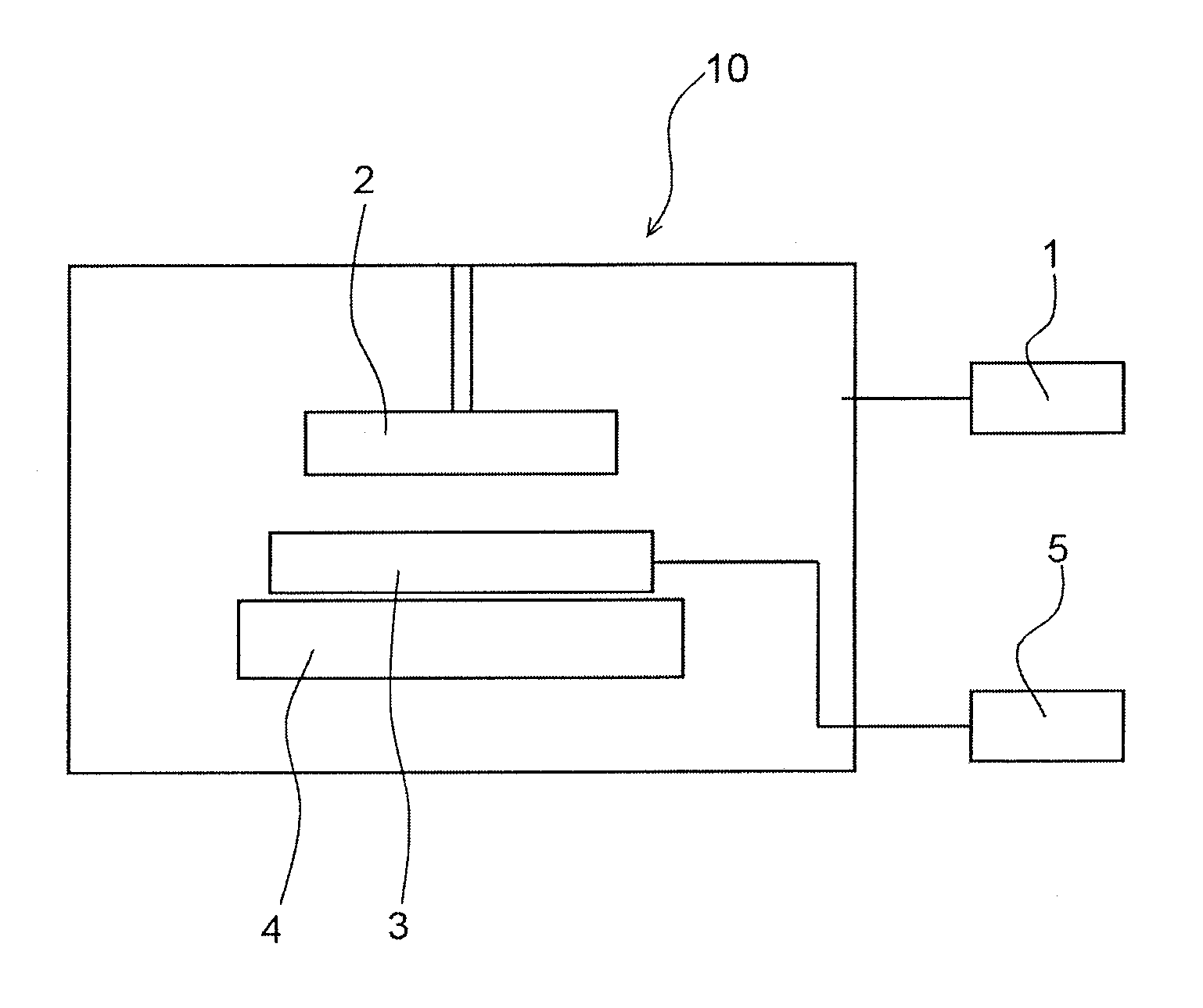
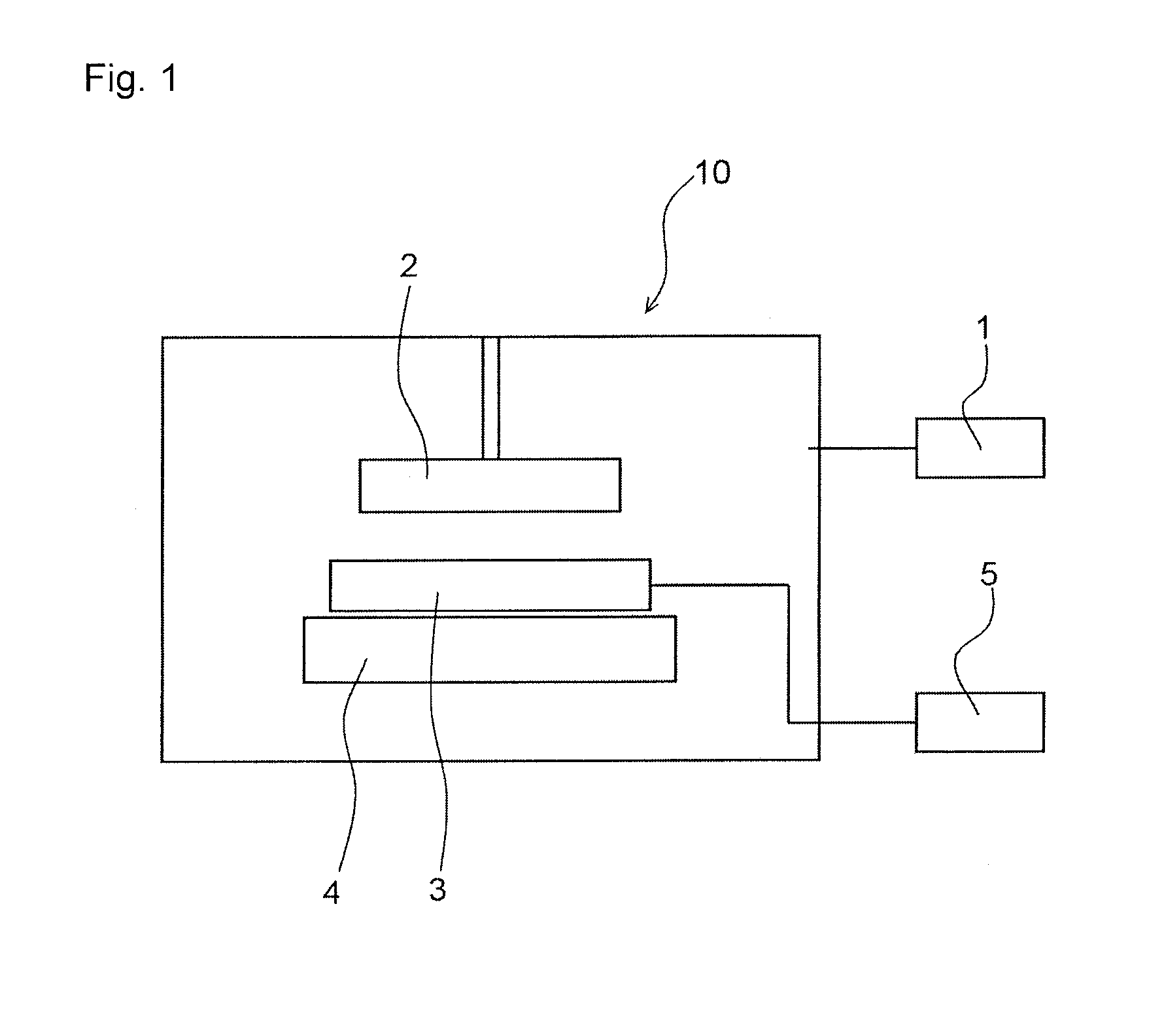
[0042]20 units of the anode body were welded to the substrate so that the powder sintered body parts of the anode body lie in a straight line and the substrate was fastened to the holder of the dipping device. An aqueous dispersion liquid of the conductive polymer (poly-(3,4-ethylenedioxyth...

example 2

[0047]20 units of solid electrolytic capacitors were produced by the same operation as in Example 1 except that an aqueous dispersion liquid of conductive polymer (poly-(3,4-ethylenedioxythophene)) having an average particle diameter of 20 nm adjusted to have a solid content of 2.3% and the viscosity of 60 mPa / s was used instead of the aqueous dispersion liquid of conductive polymer (poly-(3,4-ethylenedioxythophene)) having an average particle diameter of 20 nm adjusted to have a solid content of 1.1% and the viscosity of 30 mPa / s. The average capacitance at 120 Hz and equivalent series resistance at 10 kHz of the obtained capacitors are shown in Table 1.

example 3

[0048]A manganese dioxide layer was formed on the dielectric layer of the anode body by the same operation as in Example 1 except that 30% manganese nitrate solution was used instead of the aqueous dispersion liquid of conductive polymer, and the drying was performed under conditions at 200° C. for 25 minutes. Also, at the end of the fifth, tenth, fifteenth, twentieth and twenty-fifth dipping, the step of repairing the damage of the dielectric layer resulting from forming the manganese dioxide layer was added by subjecting the anode body to chemical formation in 1% phosphoric acid solution at 80° C. and 15 V for 30 minutes.

[0049]The average capacitance at 120 Hz and equivalent series resistance at 10 kHz of the thus-obtained capacitors are shown in Table 1.


PUM

PropertyMeasurementUnit
diameteraaaaaaaaaa
pore diameteraaaaaaaaaa
pressureaaaaaaaaaa

Abstract

The present invention relates to a method to produce a solid electrolytic capacitor by forming a dielectric layer on an anode body comprising a valve-acting metal sintered body having fine pores and forming on the dielectric layer a conductive compound layer to form a cathode, wherein a cathode is formed by repeating the step of dipping the anode body into an inorganic compound solution, an organic compound solution or a conductive-polymer compound dispersion liquid which turns into a conductive compound layer to thereby laminate a conductive layer on the anode body, and the depth of the anode body to be dipped is increased with each dipping; and an apparatus to be used for the method. According to the present invention, a satisfactory cathode layer can be efficiently formed and a solid electrolytic capacitor having a large capacitance and a low equivalent series resistance can be produced.

Description

TECHNICAL FIELD[0001]The present invention relates to a method for producing a solid electrolytic capacitor, a capacitor obtained by the method and an apparatus for producing the same. Specifically, the present invention relates to a method to produce a solid electrolytic capacitor by forming a dielectric layer on an anode body comprising a valve-acting metal sintered body having fine pores and forming on the dielectric layer a conductive compound layer to serve as a cathode, wherein the distance (depth) of dipping is increased with each dipping of the valve-acting metal sintered body into an inorganic compound solution, an organic compound solution or a conductive-polymer compound dispersion liquid which turns into a conductive compound layer so that the apertures on the surface of the sintered porous body may not be completely closed to thereby makes it possible to form a cathode efficiently by delivering the solution to the depth until a conductive compound layer is sufficiently ...

Claims


Application Information

Patent Timeline
Patent Type & Authority Applications(United States)
IPC IPC(8): H01G9/00H01G13/00H01G9/028H01G9/04H01G9/052
CPCH01G9/0032H01G9/0036H01G9/0425H01G13/00H01G11/48H01G11/56Y02E60/13Y10T29/417Y10T29/435
Inventor SHIBUYA, YOSHINORI
Owner RESONAC CORP
Why Eureka
Try Eureka