Electronic apparatus with a cooling redundancy function

a technology of redundancy function and electrical equipment, which is applied in the direction of electrical apparatus casing/cabinet/drawer, instrument, and solid-state device details, etc., can solve the problems of increasing the size of the apparatus, increasing the noise and the price of the apparatus due to an increase in the number of cooling fans, and achieving high reliability, reducing the number of cooling fans, and reducing the size of the cooling fan.

Active Publication Date: 2006-08-29
FUJITSU LTD
View PDF4 Cites 15 Cited by
  • Summary
  • Abstract
  • Description
  • Claims
  • Application Information

AI Technical Summary

Benefits of technology

[0017]Accordingly, it is a general object of the present invention to provide an electronic apparatus in which the above-described disadvantages are eliminated.
[0018]A more specific object of the present invention is to provide a cooling redundancy function for multiple cooling fans with simple structure in an electronic apparatus in which the same or different multiple units equipped with cooling fans are mounted, and to realize reduction in the price, size, and noise of the electronic apparatus.
[0021]Thus, according to the present invention, in an electronic apparatus receiving two or more units in a shelf part thereof, an opening through which the space inside each unit communicates with the space inside the shelf part is formed in one or more third faces of the unit, the third faces being different from the front and rear faces of the unit. As a result, it is possible to reduce the number of cooling fans mounted in each unit to one while ensuring the cooling redundancy function for the multiple units. Accordingly, it is possible to realize an electronic apparatus reduced in size, noise, and price while maintaining its high reliability. There is no need to attach a cooling fun for redundancy to each unit as a method of providing the cooling redundancy function for the multiple units mounted in the electronic apparatus. Therefore, an electronic apparatus reduced in price, size, and noise can be realized with simple structure. In the case of a large-scale computer system, it is possible to avoid system failure even if several cooling fans fail simultaneously. Thus, a low-cost electronic apparatus with a highly reliable cooling redundancy function can be provided.

Problems solved by technology

However, in exchange for an improvement in reliability due to the cooling redundancy function, the mounting of multiple cooling fans in each unit causes an increase in the size of the apparatus as well as an increase in the noise and the price of the apparatus due to an increase in the number of cooling fans.

Method used


Image

  • Electronic apparatus with a cooling redundancy function
  • Electronic apparatus with a cooling redundancy function
  • Electronic apparatus with a cooling redundancy function

Examples


first embodiment

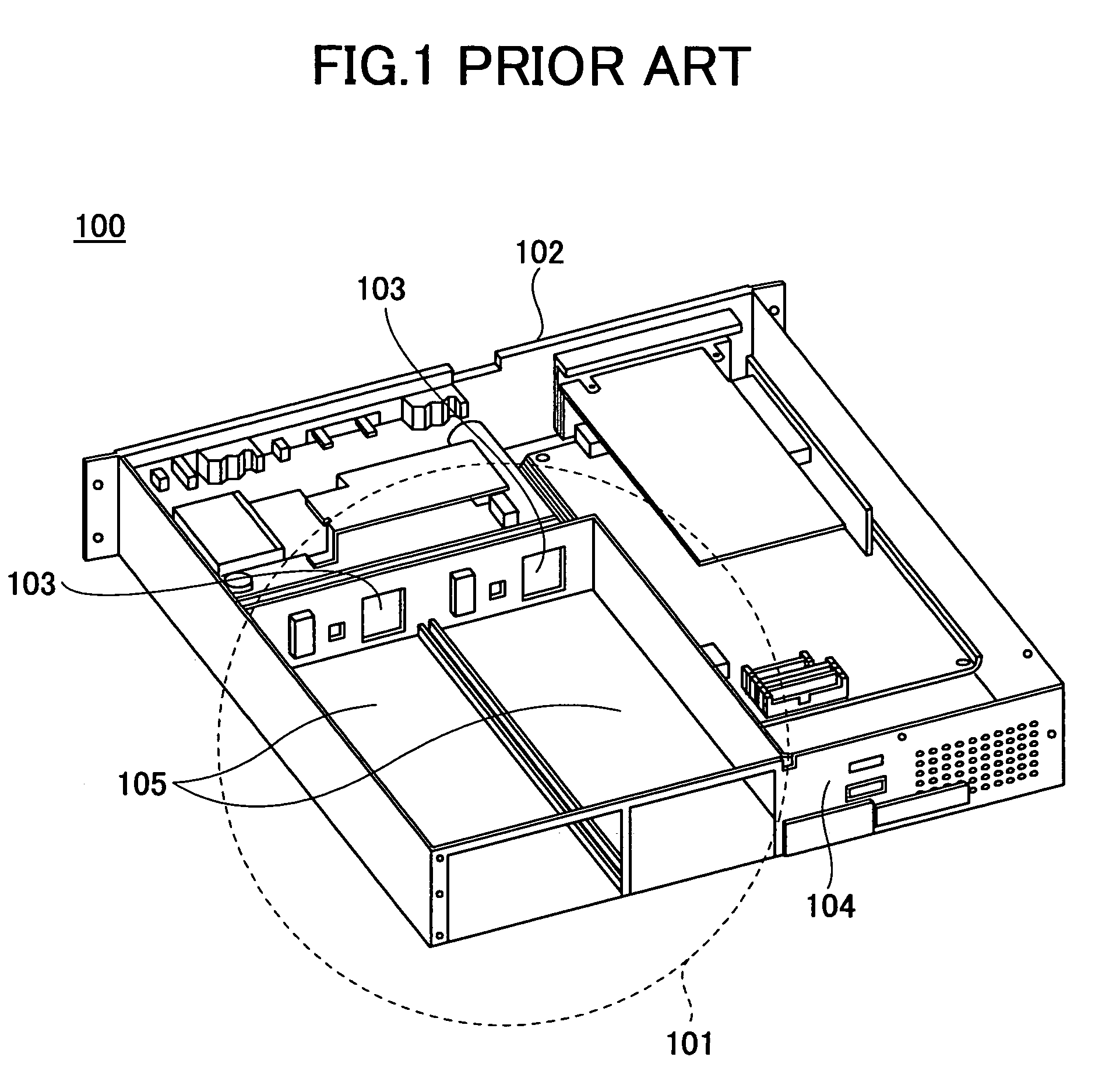
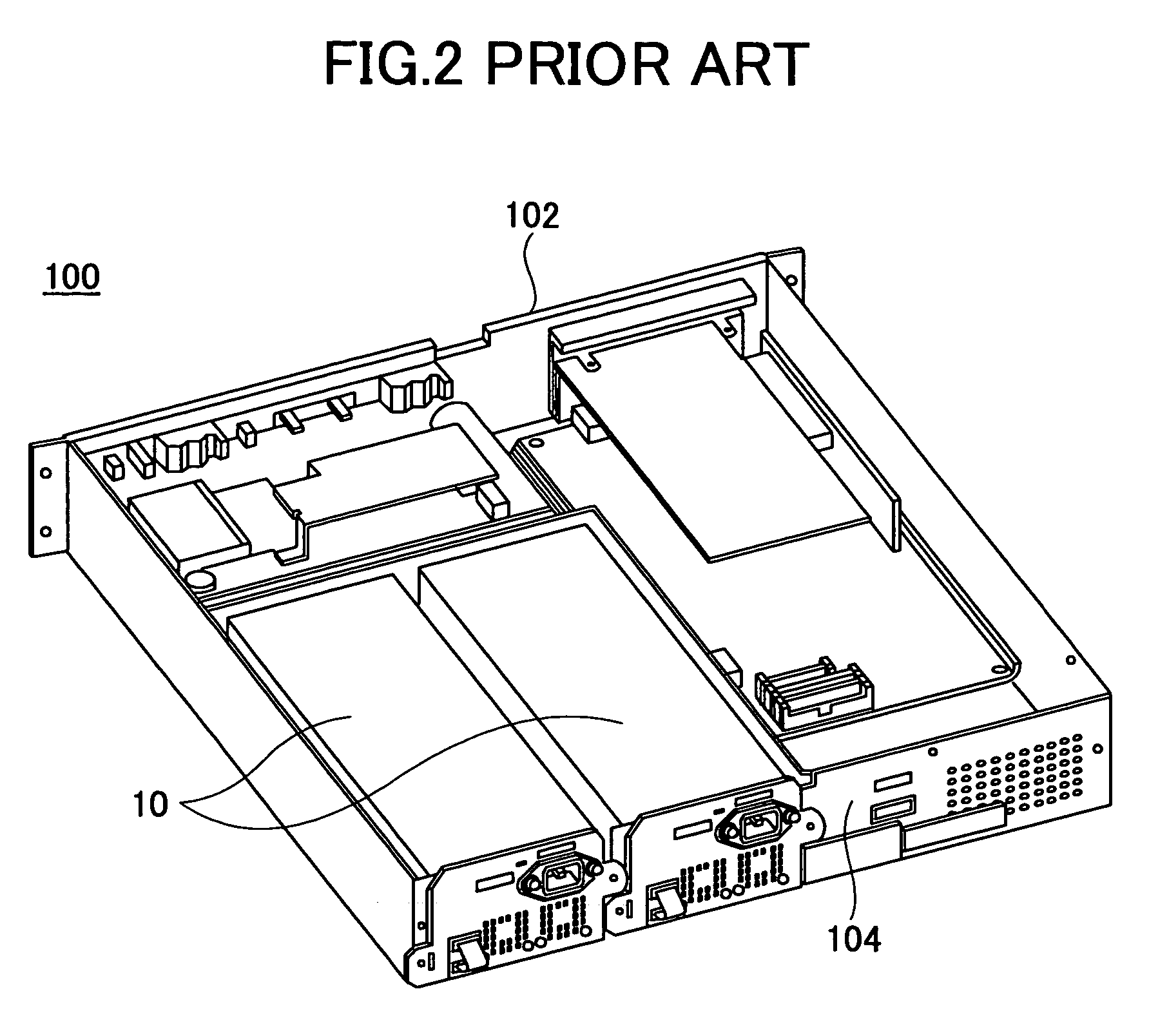
[0039]FIG. 6 is a perspective view of an electronic apparatus 100A according to the present invention, showing a state before multiple units 20 according to this embodiment are mounted in the shelf part 101. FIG. 7 shows a state where the multiple units 20 are mounted in the shelf part 101 of the electronic apparatus 100A of FIG. 6.

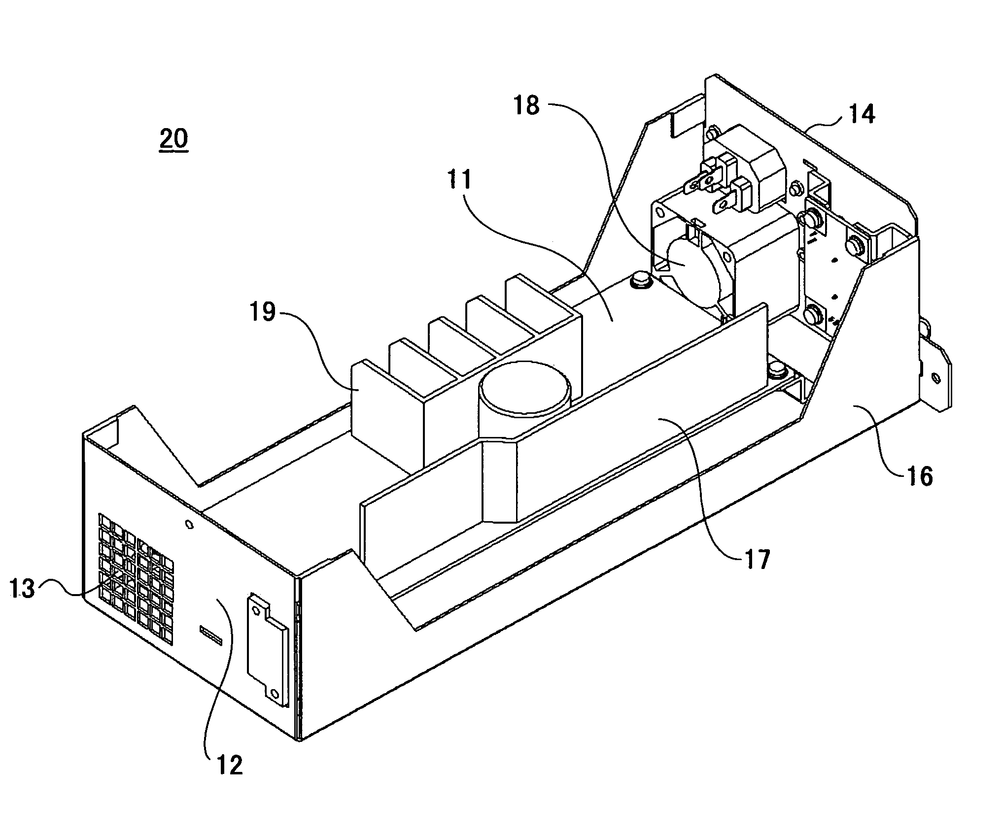
[0040]FIGS. 8A and 8B are top perspective views of one of the multiple units 20 to be mounted in the electronic apparatus 100A according to this embodiment, showing the configuration thereof. FIG. 8A shows the front-side appearance of the unit 20, and FIG. 8B shows the rear-side appearance of the unit 20.

[0041]In the illustrated embodiment, the multiple units 20 are mounted parallel to each other in the shelf part 101 of the electronic apparatus 100A as shown in FIG. 7.

[0042]The unit 20 shown in FIGS. 8A and 8B is, for instance, a power supply unit to be mounted in a computer main body. The unit 20 includes a single cooling fan 18 (FIG. 9) to provide the ...

second embodiment

[0058]FIGS. 12A and 12B are top perspective views of one of multiple units 20A to be mounted in the electronic apparatus 100A according to the present invention. FIG. 12A shows the front-side appearance of the unit 20A, and FIG. 12B shows the rear-side appearance of the unit 20A.

[0059]Like the above-described units 20 (FIGS. 6A and 6B), in the illustrated embodiment, the multiple units 20A are mounted parallel to each other in the shelf part 101 of the electronic apparatus 100A as shown in FIG. 7 according to this embodiment.

[0060]The unit 20A shown in FIGS. 12A and 12B is, for instance, a power supply unit to be mounted in a computer main body. The unit 20A includes the single cooling fan 18 (FIG. 9) to provide the cooling redundancy function. The unit 20A includes the inlet 13 formed in the front face 12, the outlet 15 formed in the rear face 14 opposite the front face 12, and the single cooling fan 18. The cooling fan 18 draws in cooling air from outside through the inlet 13 and ...

third embodiment

[0066]FIG. 13 is a perspective view of another configuration of the multiple units 20 mounted in an electronic apparatus 100B according to the present invention.

[0067]In the electronic apparatus 100B of FIG. 13, the three units 20 are mounted in the same shelf part 101 so that each adjacent two of the units 20 are disposed parallel to each other. As shown in FIG. 9, each unit 20 has the single cooling fan 18 attached thereto. The cooling redundancy openings 16h are formed in the corresponding third faces 16 different from the face on which the cooling fan 18 is attached (the rear face 14) and the face in which the inlet 13 is formed (the front face 12). The opening 101h (FIG. 6) for letting in cooling air is formed in the shelf part 101 of the electronic apparatus 100B at a position corresponding to a corresponding one of the cooling redundancy openings 16h. This opening 101h may comprise multiple small holes as the cooling redundancy openings 16h. The space inside each unit 20 comm...


PUM


Abstract

An electronic apparatus includes a shelf part and multiple units mounted in the shelf part. Each unit includes first and second faces opposite each other, a cooling fan, and a third face different from the first and second faces. The first face has an inlet and the second face has an outlet. A cooling fan cools a circuit board inside the unit by letting in cooling air from outside through the inlet and letting out the cooling air through the outlet. The third face has an opening so that the space inside the unit communicates with the space inside the shelf part through the opening.

Description

BACKGROUND OF THE INVENTION[0001]1. Field of the Invention[0002]The present invention relates generally to electronic apparatuses forming computer systems, and more particularly to a cooling redundancy function suitable for an electronic apparatus in which the same or different multiple units equipped with cooling fans are mounted.[0003]2. Description of the Related Art[0004]As a result of recent developments in computer systems, electronic apparatuses forming computer systems are required to be increased in reliability, and are also required to be reduced in price and size in order to be more competitive on the market. Accordingly, it is necessary to realize highly reliable electronic apparatuses reduced in price and size.[0005]In a conventional electronic apparatus in which the same or different multiple units equipped with cooling are mounted, multiple cooling fans are provided in each unit in order to increase the reliability of the electronic apparatus. For instance, Japanese L...

Claims


Application Information

Patent Timeline
Patent Type & Authority Patents(United States)
IPC IPC(8): H05K7/20G06F1/20
CPCG06F1/184H05K7/2019G06F1/20G06F1/188
Inventor ISHIYAMA, KAZUNORI
Owner FUJITSU LTD
Why Eureka
Try Eureka