Wireless communication system and method of controlling same

a communication system and wireless technology, applied in the field of wireless communication system, can solve the problems of limiting the transmission rate, limiting the number of connecting devices that can be accommodated by the main unit, and limiting the number of wireless telephones

Inactive Publication Date: 2006-08-29
CANON KK
View PDF31 Cites 25 Cited by
  • Summary
  • Abstract
  • Description
  • Claims
  • Application Information

AI Technical Summary

Benefits of technology

[0040]An object of the present invention is to provide a wireless communication system in which selection of communication means conforming to a communication request and status of communication is possible.
[0041]Another object of the present invention is to reduce the load upon the main unit in communication between extensions.
[0042]A further object of the present invention is to make it possible for the main unit to implement centralized administration of wireless terminals and wireless channels used in a wireless communication system.

Problems solved by technology

As a result, the transmission rate is limited and, hence, the audio from a plurality of wireless telephones cannot be multiplexed using a single carrier frequency.
There is also a limit upon the number of connecting devices that can be accommodated by the main unit and upon the number of wireless telephones that can be accommodated.
This means that the main unit cannot determine whether this wireless channel is currently being used or is incapable of being used because of disturbing waves.
Further, in the case where wireless telephones place extension calls to each other directly, the status of use of the wireless telephones and the status of use of the wireless channels cannot be managed by the main unit.
Furthermore, since a wireless telephone J3 communicates using the wireless channel which it itself acquired, control information cannot be received from the main unit.

Method used


Image

  • Wireless communication system and method of controlling same
  • Wireless communication system and method of controlling same
  • Wireless communication system and method of controlling same

Examples


first embodiment

[0086][First Embodiment]

[0087]One type of digital wireless communication that has become the focus of attention in recent years is spread-spectrum communication. In spread-spectrum communication, the information transmitted is spread over a wide bandwidth. This provides the advantages of improved interference avoidance and security. At the present time, frequencies in the 2.4 GHz band have been allocated for spread-spectrum communication in various countries and the use of spread-spectrum communication is growing world-wide.

[0088]Spread-spectrum communication is broadly divided into frequency hopping (FH) and direct sequence (DS). In FH, transmission using a wide band is performed by changing the modulating frequency within a fixed period of time. In DS, a wide band is used by spreading and modulating the information for transmission using a pseudo-noise code having a rate which is ten times to several hundred times the rate of the information.

[0089]In this embodiment, a case will b...

second embodiment

[0269][Second Embodiment]

[0270]A second embodiment of the invention will now be described. Since the architecture of the wireless communication system according to this embodiment and the construction of the terminals, etc. constituting the system are similar to those of the system according to the first embodiment described above, these need not be illustrated or described again.

[0271]Here will be described processing for terminating a call on an outside line at the time of communication between extensions.

[0272]In the first embodiment, outside-line processing is performed separately of extension processing in regard to processing executed when an incoming call to a wireless telephone is terminated and processing executed when there is a call between extensions. However, in a case where a call is terminated on an outside line during an extension call, an incoming-call display is presented on the display unit 413 of the wireless telephone 3. To accomplish this, third communication m...

third embodiment

[0283][Third Embodiment]

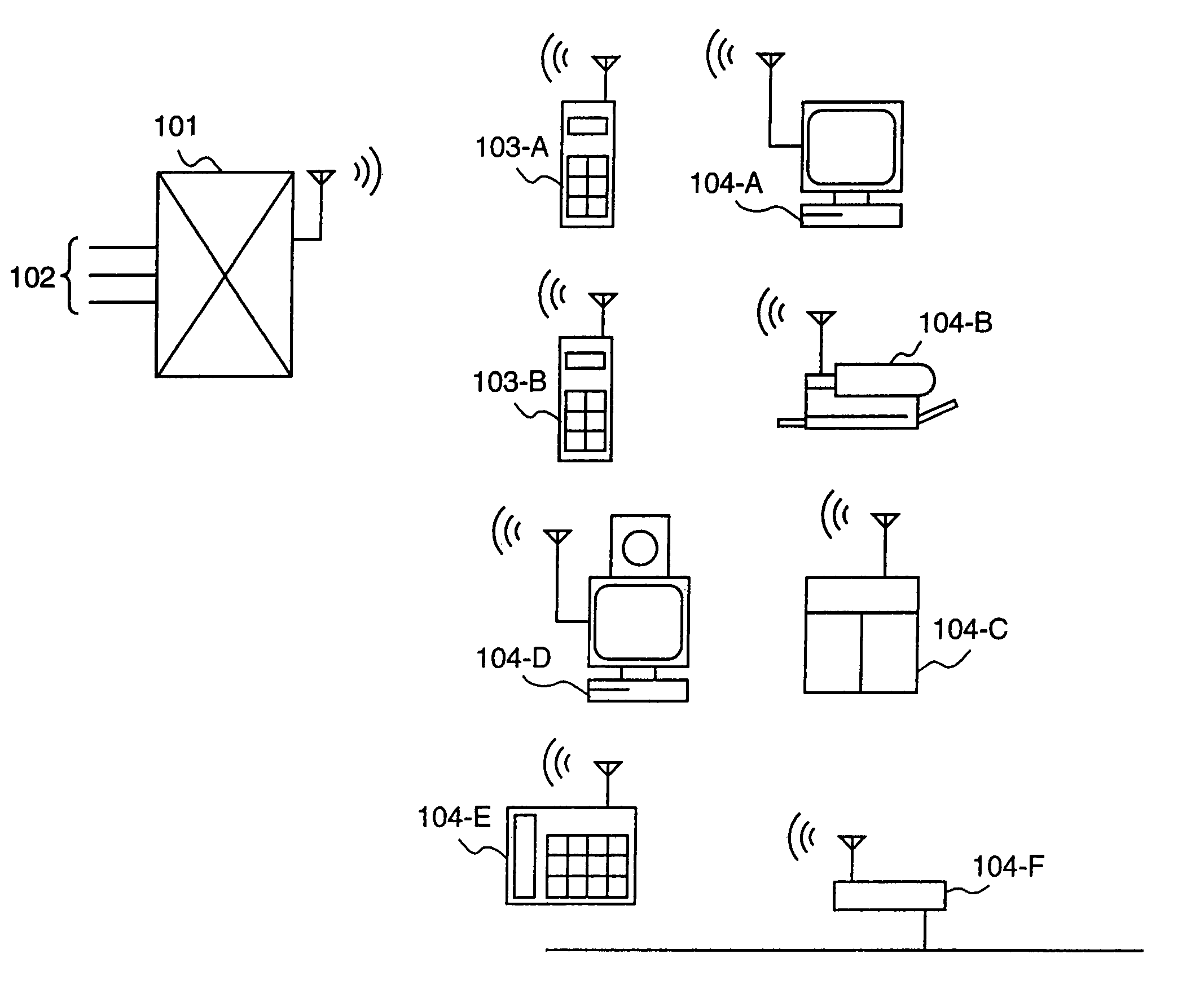
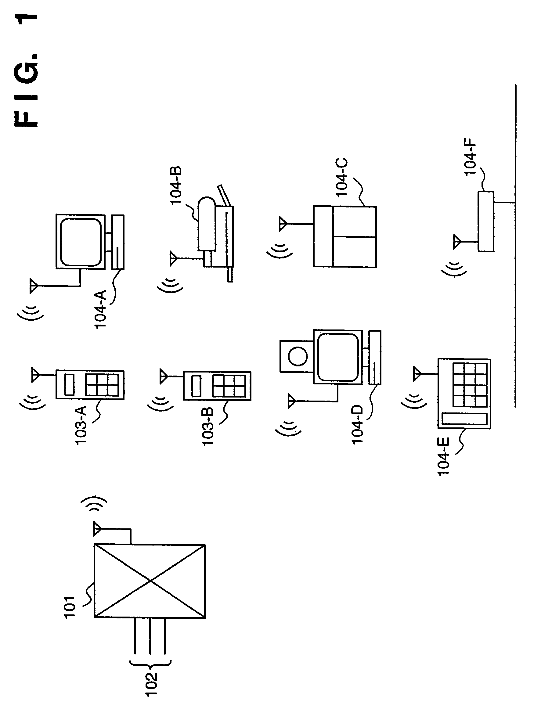
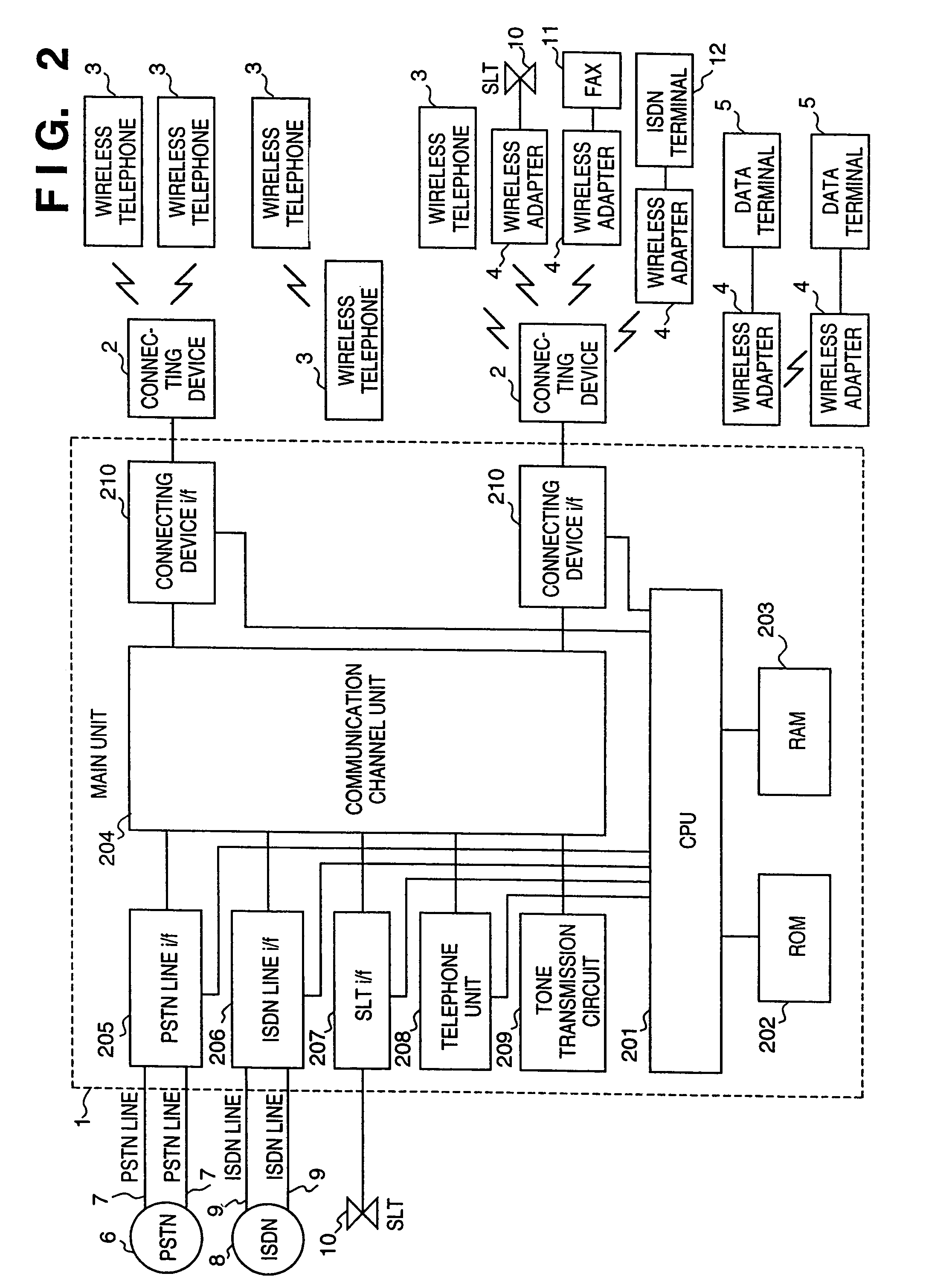
[0284]In the first and second embodiments, a low-speed frequency hopping method is used. However, effects similar to those of these embodiments can be expected even if the direct sequence method is used. This can be realized by using the direct sequence method in the connecting device 2 of the main unit, the wireless telephone 3 and the wireless portion of the wireless adapter 4 of the system illustrated in FIG. 2.

[0285]FIG. 31 shows an example of a communication procedure for a case in which the direct sequence method is used. First, communication is divided between a main-unit transmission frame and a slave transmission frame along the time axis. In other words, the main-unit transmission frame and the slave transmission frame are sent in alternating fashion.

[0286]FIG. 32 is a diagram showing an example of the frame transmitted by the main unit. This frame has control information and time slots for each of the wireless terminals. In FIG. 32, FSYN represents...


PUM


Abstract

A wireless communication system has a plurality of wireless communication devices capable of communicating with one another directly without the intervention of another device, and a wireless control unit which accommodates these wireless communication devices. The wireless control unit manages the direct communication among the wireless communication devices as well as communication between the wireless control unit and the wireless communication devices.

Description

[0001]This is divisional of application Ser. No. 09 / 785,174, filed Feb. 20, 2001 now U.S. Pat. No. 6,804,289, which is a divisional of Ser. No. 08 / 651,035, filed May 17, 1996 now U.S. Pat. No. 6,263,210.BACKGROUND OF THE INVENTION[0002]1. Field of the Invention[0003]This invention relates to a wireless communication system in which switching is performed among terminals or between terminals and a public line in wireless fashion, as well as to a method of controlling this system.[0004]2. Description of the Related Art[0005]Wireless communication is rapidly becoming more widespread and is finding use in a variety of fields. Telephone exchanges are no exception, and systems have been proposed in which communication between a main unit having a switching function and wireless telephones dedicated to the system (hereinafter referred to as wireless telephones) is performed in wireless fashion.[0006]A wireless telephone exchange according to the prior art will now be described.[0007]<Sy...

Claims


Application Information

Patent Timeline
Patent Type & Authority Patents(United States)
IPC IPC(8): H04B1/707H04B1/713H04B1/7136H04B1/715H04B7/24H04M1/724H04M1/72412H04M1/725H04M1/72505H04M1/72513H04M1/733H04W76/02H04W84/10H04W84/12H04W88/14
CPCH04M1/725H04M1/72505H04W84/10H04M1/72519H04M1/7253H04M1/733H04B2001/71365H04B2001/7154H04M1/72513H04M1/72412H04M1/724
Inventor TAKAHASHI, TAKUMI
Owner CANON KK
Why Eureka
Try Eureka