Telephone headset

Inactive Publication Date: 2006-08-29
UNAX CORP
View PDF6 Cites 44 Cited by
  • Summary
  • Abstract
  • Description
  • Claims
  • Application Information

AI Technical Summary

Benefits of technology

[0008]Yet another aspect of the invention is that the mounting ring is movably attached to the ear support by a spring biased ball and socket joint. The combination of flexible joints and removability of the earphone provides the degrees of freedom necessary to permit the earphone to be worn comfortably on either ear of the wearer. The earphone is biased toward the plane of the head to provide good acoustic coupling with the ear.
[0009]Still another aspect of the invention is that a strain relief for the electrical connections is attached to the earphone which directs the electrical connections toward the plane of the head. This configuration eliminates a torque which otherwise would tend to disl

Problems solved by technology

However, the boom microphone and the electrical cable apply torques to the ear support which tends to

Method used


Image

  • Telephone headset
  • Telephone headset
  • Telephone headset

Examples


Embodiment Construction

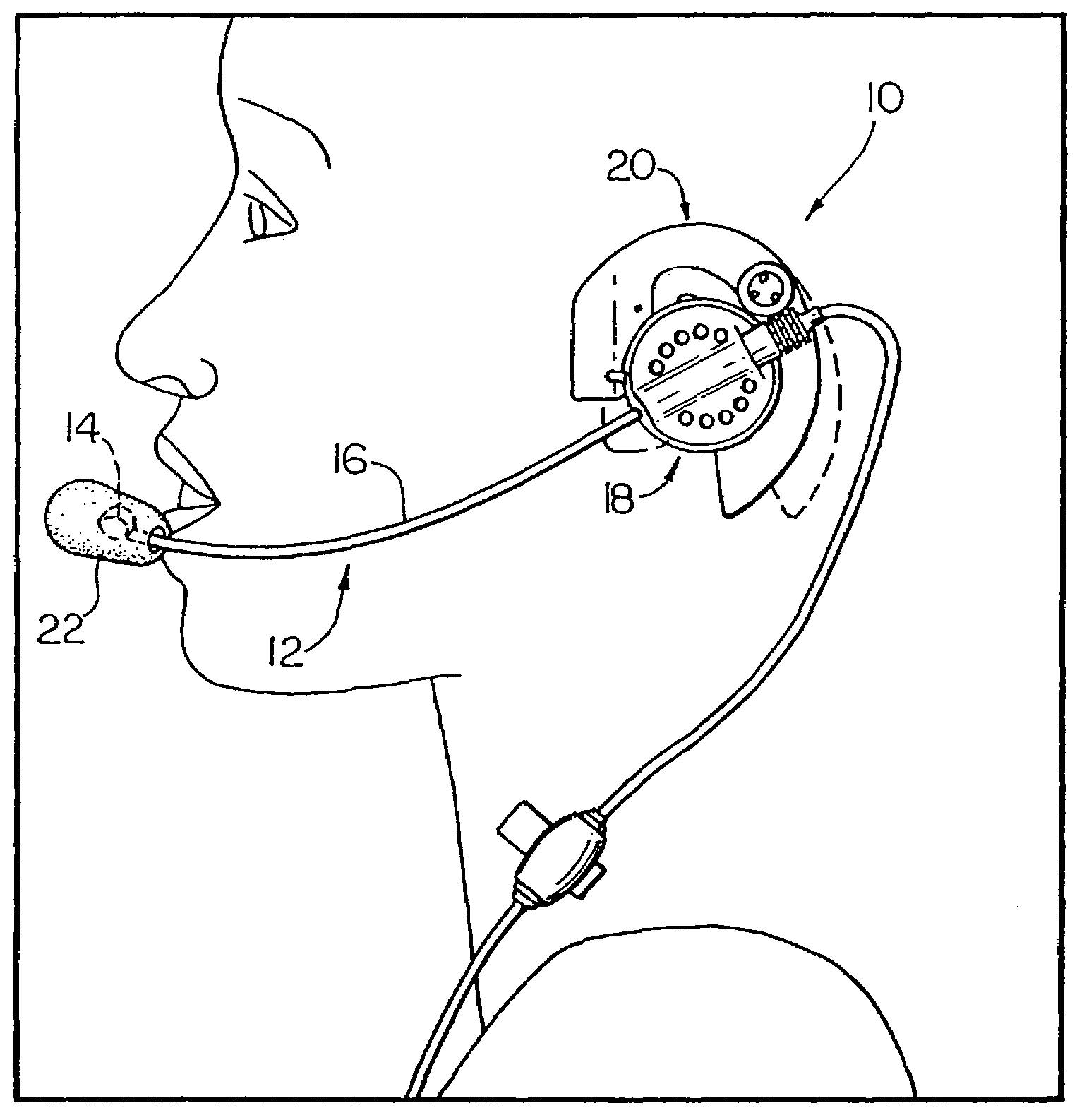
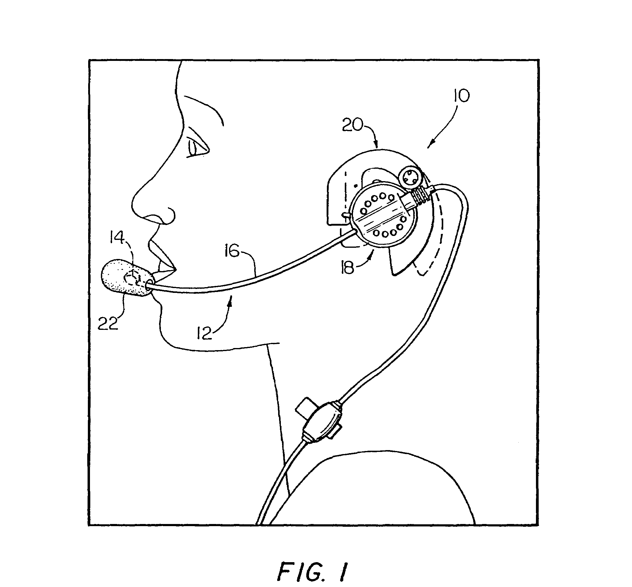
[0022]In brief overview, and referring to FIG. 1, a telephone headset 10 constructed in accordance with the invention, includes a boom microphone portion 12; a earphone portion 18; and an ear support portion 20. The boom microphone portion 12 includes a microphone portion 14 (shown in phantom enclosed in a foam shield 22) positioned at one end of a hollow microphone boom 16. The other end of the microphone boom 16 is movably attached to the earphone portion 18. The ear support portion 20, which is removably attached to the earphone portion 18, rests on the operator's ear in a manner that positions the earphone portion 18 adjacent the operator's ear and the microphone portion 14 adjacent the operator's mouth.

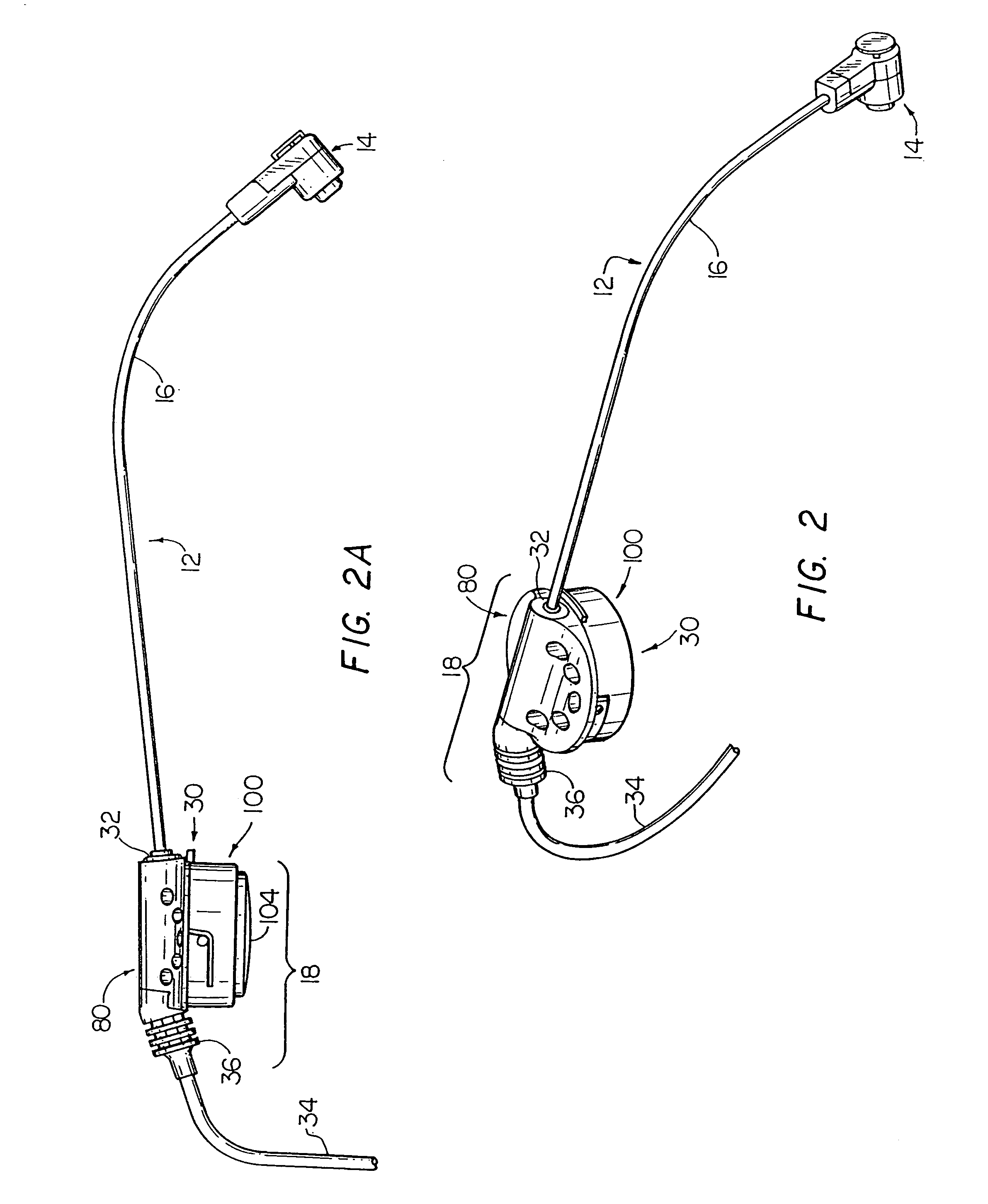
[0023]Referring to FIGS. 2 and 2a, the microphone boom 16 is attached to one side of an earphone housing assembly 30 of the earphone portion 18 by a ball joint assembly 32 about which more will be said below. Electrical signals are supplied to the earphone portion 18 and received...


PUM


Abstract

A telephone headset including a boom microphone, an earphone, and an ear support constructed and arranged to be adjusted and comfortable for a wearer. The headset is configured with an adjustable ear support to fit a variety of ear sizes without affecting the balance of the ear support on the ear of the wearer. The ear support includes a rotational hinge which is biased into a given position by a compression washer. The earphone is removably and adjustably attached to a mounting ring which in turn is smoothly is movably attached to the ear support by a spring biased ball and socket joint. The combination of flexible joints and removability of the earphone provides the degrees of freedom and striction necessary to permit the earphone to be worn comfortably on either ear of the wearer. A strain relief for the electrical connections is attached to the earphone which directs the electrical connections toward the plane of the head, thereby eliminating a torque which otherwise would tend to dislodge the ear support from the ear. The earphone includes a series of openings in its rear surface to maximize its acoustics. The boom microphone includes a spring biased ball and socket joint to movably fix the orientation of the microphone with respect to the wearer to a good comfort level. The boom microphone ball and socket joint is configured with a tab and stop to prohibit 360 degree rotation of the boom to prevent strain on the electrical connections to the microphone.

Description

FIELD OF THE INVENTION[0001]The present application is a continuation of application Ser. No. 09 / 591,881, filed Jun. 12, 2000 now U.S. Pat. No. 6,377,684, which is a continuation of application Ser. No. 08 / 668,599, filed Jun. 18, 1996, now issued as U.S. Pat. No. 6,097,809, which is a continuation of application Ser. No. 08 / 505,115, filed Jul. 21, 1995, now abandoned, which is a division of Ser. No. 08 / 231,981, filed Apr. 21, 1994, now issued as U.S. Pat. 5,446,788, which is a continuation of application Ser. No. 07 / 952,967, filed Sep. 29, 1992, now abandoned.[0002]The invention relates to the field of telephone headsets and more particularly to telephone headsets having an ear support.BACKGROUND OF THE INVENTION[0003]Telephone headsets permit the use of a telephone microphone and earphone while freeing the user's hands for other activities such as note taking and computer keyboard entry. The earliest forms of headsets included an earphone portion which included an over-the-head ban...

Claims


Application Information

Patent Timeline
IPC IPC(8): H04M9/00H04M1/05
CPCH04M1/05H04R1/105H04R1/1066H04R2201/107H04R1/1058
Inventor LUCEY, ROBERT E.ELA, JOHNLADA, CHRISTOPHER O.SHUBERT, LAWRENCE G.LOEW, CHRISTOPHER
Owner UNAX CORP
Why Eureka
Try Eureka