Method for producing an ultrasonic transducer core with embedded piezoelectric transducer elements

A piezoelectric transducer and converter technology, which is applied to fluids, instruments, and measuring devices that utilize vibration, and can solve problems such as system design limitations, ultrasonic sensor damage, and easy drift.

Active Publication Date: 2019-02-19
ROBERT BOSCH GMBH
View PDF7 Cites 0 Cited by
  • Summary
  • Abstract
  • Description
  • Claims
  • Application Information

AI Technical Summary

Problems solved by technology

[0003] A disadvantage of many known ultrasonic flowmeters is that, at least in the case of media in gaseous form, in the case of a small signal path, that is to say a small change in the running time, the change in the running time makes the method slow down. It is often very easy to drift when the rate is small
It is therefore difficult to achieve or even improve the usual tolerances in thermodynamic flow measurements
[0009] That is to say, a disadvantage of the known systems is that these systems are usually strongly subject to design constraints
The disadvantage of embedding the piezoelectric transducer element directly in the adaptation layer is that the piezoelectric transducer element differs from the adaptation body with regard to the coefficient of thermal expansion, which affects the ultrasonic waves, especially during cooling and / or multiple temperature cycles. Converter Cores Bring Problems
Such cracks can lead to complete damage on the ultrasonic sensor, since there is hardly any signal available for measurement due to the large acoustic impedance to be overcome

Method used


Image

  • Method for producing an ultrasonic transducer core with embedded piezoelectric transducer elements
  • Method for producing an ultrasonic transducer core with embedded piezoelectric transducer elements
  • Method for producing an ultrasonic transducer core with embedded piezoelectric transducer elements

Examples


Embodiment Construction

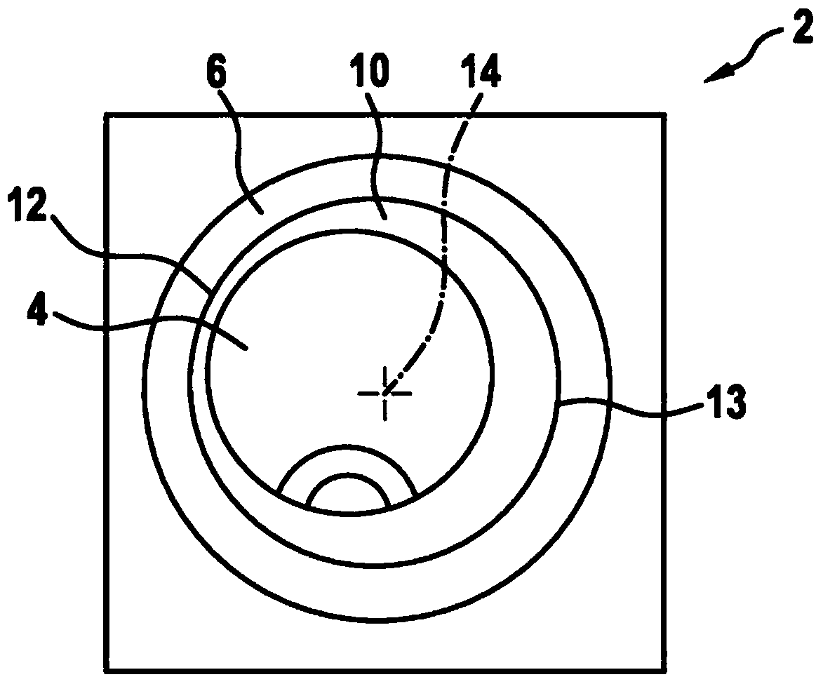
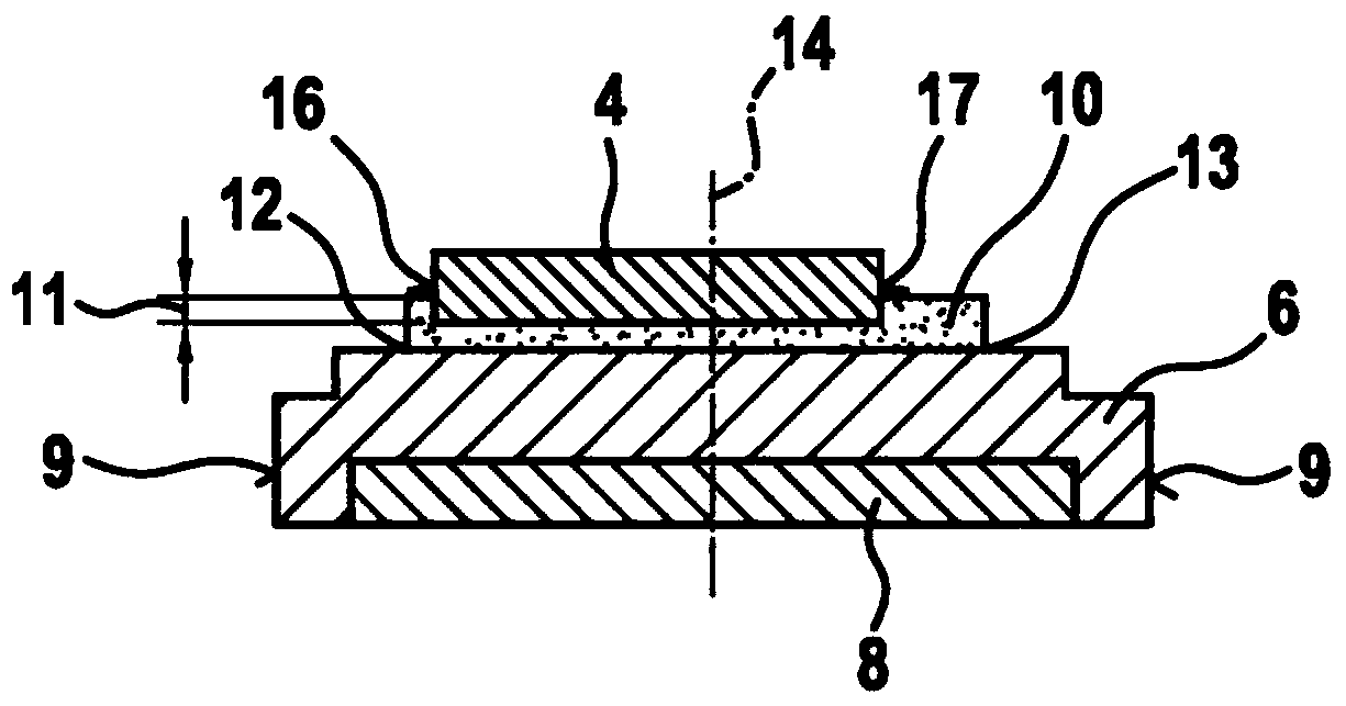
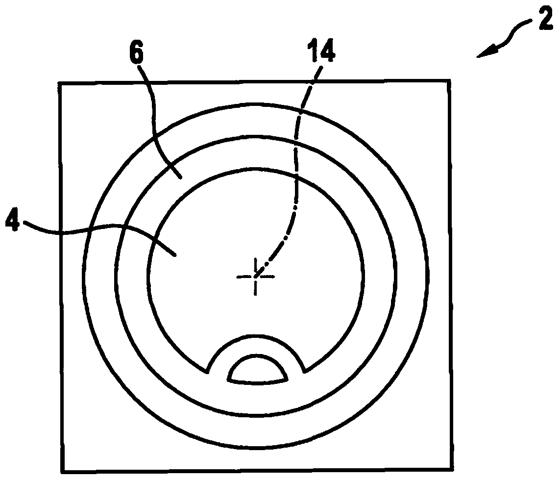
[0032] exist figure 1 and figure 2The ultrasonic transducer 2 shown in FIG. 2 comprises a piezoelectric transducer element 4 and an adaptation body 8 . An adhesive layer 10 is introduced between the adapting body 8 and the piezoelectric element 4 .

[0033] As primary electro-mechanical conversion principles, eg the electrostatic effect, the magnetostrictive effect, or the piezoelectric effect is used in the ultrasonic transducer 2 . In the case of piezoelectric ceramics as the primary converter element, different resonant vibration modes result, which, depending on the geometry, are more or less pronounced, or which are coupled differently to one another or Decoupling. In the case of simple square or cylindrical geometries, the following vibration modes can firstly be obtained, all of which can be used, at least in principle, for ultrasonic conversion:

[0034] - Thickness vibrations of thin piezoelectric sheets, wherein, in particular when the diameter of the piezoelect...


PUM


Abstract

The invention relates to a method for producing an ultrasonic converter core (2) comprising at least one piezoelectric converter element (4) and at least one adaptive body (8), for promoting a vibration coupling between the piezoelectric converter element (4) and a surrounding medium, and at least one temperature expansion compensating member (6) with the following steps: - insertion of the piezoelectric converter element (4) in a moulding tool; - insertion of the adaptive body in the moulding tool; - insertion of a moulding mass in the moulding tool such that the moulding mass forms a force-fit connection, a chemical bond and / or a form-fit connection with the adaptive body (8) and the piezoelectric converter element (4); and - hardening of the moulding mass for the formation of the temperature expansion compensating member (6). The invention further relates to an ultrasonic converter core (2) particularly manufactured according to the method.

Description

technical field [0001] The invention relates to a method for producing an ultrasonic transducer core and to an ultrasonic transducer core. Background technique [0002] The invention relates to an ultrasonic transducer, which is used as a flow meter, for example in the field of method technology or in the automotive field (in particular for the measurement of volume flow or mass flow in the air intake and / or exhaust of internal combustion engines); or Use as environmental sensors, in particular in the front and / or rear of the bumper of the vehicle, for example for parking assistance systems and / or collision avoidance systems. Typical ultrasonic transducers are used here: they not only transmit ultrasonic waves into a fluid medium (for example air, gas and / or liquid), but also receive ultrasonic waves. Ultrasonic signals are usually transmitted via a fluid medium from the transmitter to the receiver or from the transmitter into the environment and the reflected ultrasound si...

Claims


Application Information

Patent Timeline
Patent Type & Authority Patents(China)
IPC IPC(8): G01F1/66B06B1/06
CPCB06B1/067G01F1/662
Inventor J·瓦尔特H·劳施
Owner ROBERT BOSCH GMBH
Why Eureka
Try Eureka