
Improvements in or relating to the monitoring of fluid pipes

a technology for fluid pipes and monitoring devices, applied in the direction of fluid tightness measurement, optical apparatus testing, instruments, etc., can solve the problems of difficult to identify a problem more, and inaccessible pipes to visual inspection, etc., to achieve the effect of neutral buoyancy

Active Publication Date: 2021-05-13
CRALEY GRP
View PDF1 Cites 0 Cited by
  • Summary
  • Abstract
  • Description
  • Claims
  • Application Information

AI Technical Summary

Benefits of technology

The patent is about a way to put a special fiber inside a pipe to monitor its condition. This is important because the fiber is protected from damage and can detect things like pressure waves, temperature changes, and vibrations. The method also includes sending a signal to make sure the vibration is still working correctly. This makes it easier to monitor the pipe's condition and can help prevent accidents.

Problems solved by technology

In many cases, pipes are not accessible to visual inspection, being buried underground.
However sensors are widely spaced and it can therefore be difficult to identify a problem.
Additionally, where it is possible to identify a problem it may be difficult to identify the location of the problem more precisely than between two fixed sensors or an approximate distance along the pipe from a sensor location.
For instance, in water pipes existing sporadically located pressure / audio sensors might only be able to define the location of a problem with very poor locational accuracy or certainty.
Since the submersible is moving within the pipe, flow noise associated with this movement or noise associated with powering the submersible may mask sensing of relatively minor problems.
Where pipes are buried underground this may still present a significant challenge.
This technique is known as ‘pot-holing’ and can be highly time-consuming, costly and disruptive.
Such difficulties add considerably to the expense of pipe repair.
In some instances, they may lead to decisions being taken to tolerate minor leaks for some time rather than attempt repairs immediately, and, leaks particularly in metal pipes (such as corrosion holes) may deteriorate very rapidly without corrective action
Nevertheless, such exterior fibres are exposed both to accidental damage and to intentional damage.
As accessing the exterior of an existing buried pipe is difficult DAS has been applied to buried pipes by burying a DAS fibre in close proximity (typically 20-30 cm) to the pipe.
Even so, works required for burying a DAS fibre can be expensive and highly disruptive, particularly where the buried pipe runs through an urban area.
Additionally, separately buried DAS fibres suffer from limitations in sensitivity, particularly where ground conditions provide poor or highly variable acoustic coupling to the pipe.
Furthermore, such separately buried DAS fibres are still susceptible to damage.

Method used


Image

  • Improvements in or relating to the monitoring of fluid pipes
  • Improvements in or relating to the monitoring of fluid pipes
  • Improvements in or relating to the monitoring of fluid pipes

Examples


Embodiment Construction

[0045]In order that the invention may be more clearly understood one or more embodiments thereof will now be described, by way of example only, with reference to the accompanying drawings, of which:

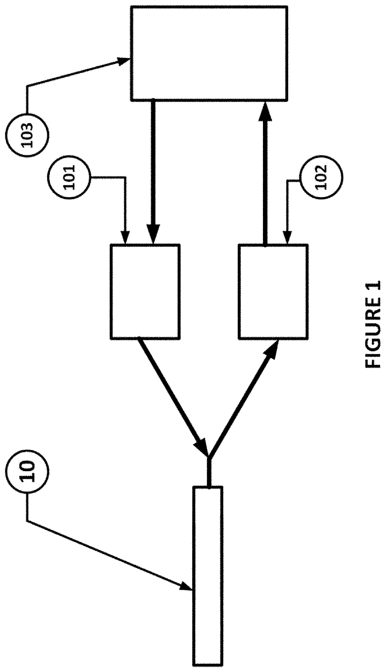
[0046]FIG. 1 is a schematic block diagram of a distributed acoustic sensing (DAS) apparatus;

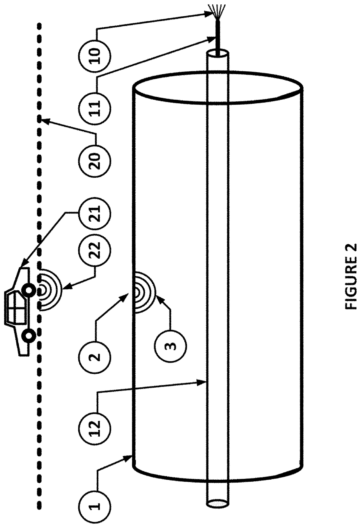
[0047]FIG. 2 is a schematic illustration of pipe monitoring using a DAS fibre according to the present invention;

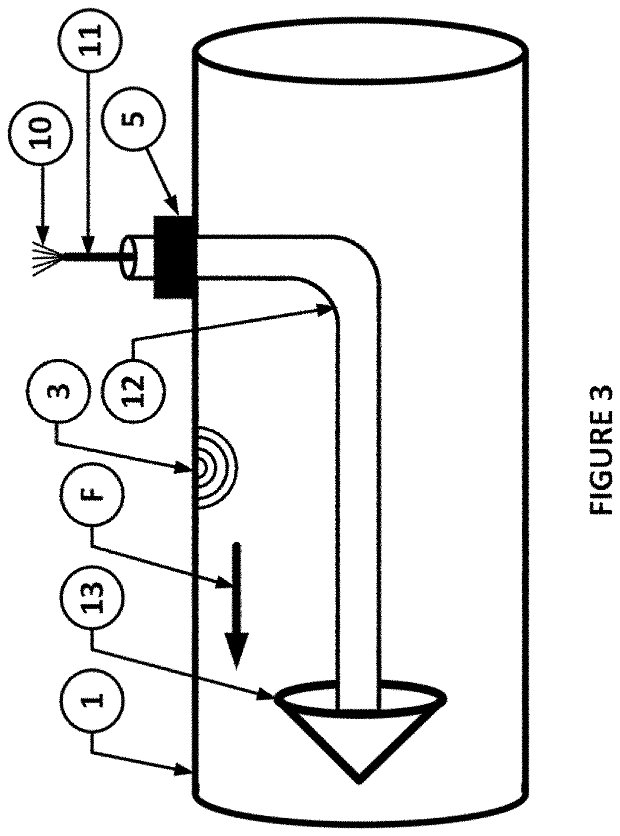
[0048]FIG. 3 is a schematic illustration of how a DAS cable may be introduced into a pipe in accordance with the present invention;

[0049]FIG. 4 is a schematic illustration of how according to the present invention a DAS cable may exit and re-enter a monitored pipe so as to avoid impacting on pipe machinery;

[0050]FIG. 5 is a schematic illustration of the use in the present invention of DAS fibre between exit from and re-entry to the pipe to monitor activity outside the monitored pipe;

[0051]FIG. 6 is a schematic illustration of an alternative implementation of pipe monitoring using a DAS f...


PUM


Abstract

A fluid pipe 1 is monitored using a distributed acoustic sensing (DAS) fibre 10 provided within pipe 1. The DAS fibre 10 is coupled at one end to a light emitter 101 and a light detector 102. The light emitter 101 emits light pulses into the DAS fibre. The light detector 102 detects backscattered light so as to provide an indication of the vibration experienced by each section of the DAS fibre 10 and thus of vibration characteristic of particular pipe events including leaks or the lie. The DAS fibre 10 in a pipe 1 can also be used to locate the route of a buried pipe 1 by successively tamping the ground surface at a number of locations A-E in the vicinity of the suspected route of the pipe 1 and comparing the tamping vibrations detected from each location A-E.

Description

TECHNICAL FIELD OF THE INVENTION[0001]The present invention relates to improvements in or relating to the monitoring of fluid pipes. In particular, the present invention relates to techniques for monitoring fluid pipes, methods of installing sensing apparatus and uses of sensing apparatus for monitoring the condition of pipes. Additionally, the present invention may further relate to the monitoring of activity adjacent to pipes and / or methods for locating pipes buried underground.BACKGROUND TO THE INVENTION[0002]Many modern services rely upon a network of pipes to carry or distribute fluids. Examples include fresh water, waste water and sewage, and fuels such as oil or gas. It is common to monitor the operation of the network and the condition of pipes. In this manner, blockages, leaks or other issues can be identified and scheduled for repair.[0003]Where pipes are provided above ground, monitoring may be achieved by visual inspection of the pipe exterior. In many cases, pipes are n...

Claims


Application Information

Patent Timeline
Patent Type & Authority Applications(United States)
IPC IPC(8): G01M3/24
CPCG01M3/243G01M3/38G01M5/0025G01M5/0033G01M5/0091G01M5/0066G01M11/086G01M11/085G01B11/00G01B17/00G01M3/047G01M11/083
Inventor PARKER, MICHAEL
Owner CRALEY GRP
Learn More