Clamping type ultrasonic flow sensor

A flow sensor, ultrasonic technology, applied in the field of ultrasonic measurement, can solve the problems of low measurement accuracy, clamping ultrasonic flow sensor is difficult to clamp, difficult to install, etc.

Active Publication Date: 2021-06-04
上海迅音科技有限公司
View PDF10 Cites 0 Cited by
  • Summary
  • Abstract
  • Description
  • Claims
  • Application Information

AI Technical Summary

Problems solved by technology

[0004] The purpose of the present invention is to provide a clamping ultrasonic flow sensor to solve the problems in the prior art that the clamping ultrasonic flow sensor is difficult to clamp on a small-diameter hose, difficult to install, low in measurement accuracy and high in production cost

Method used


Image

  • Clamping type ultrasonic flow sensor
  • Clamping type ultrasonic flow sensor
  • Clamping type ultrasonic flow sensor

Examples


Embodiment 1

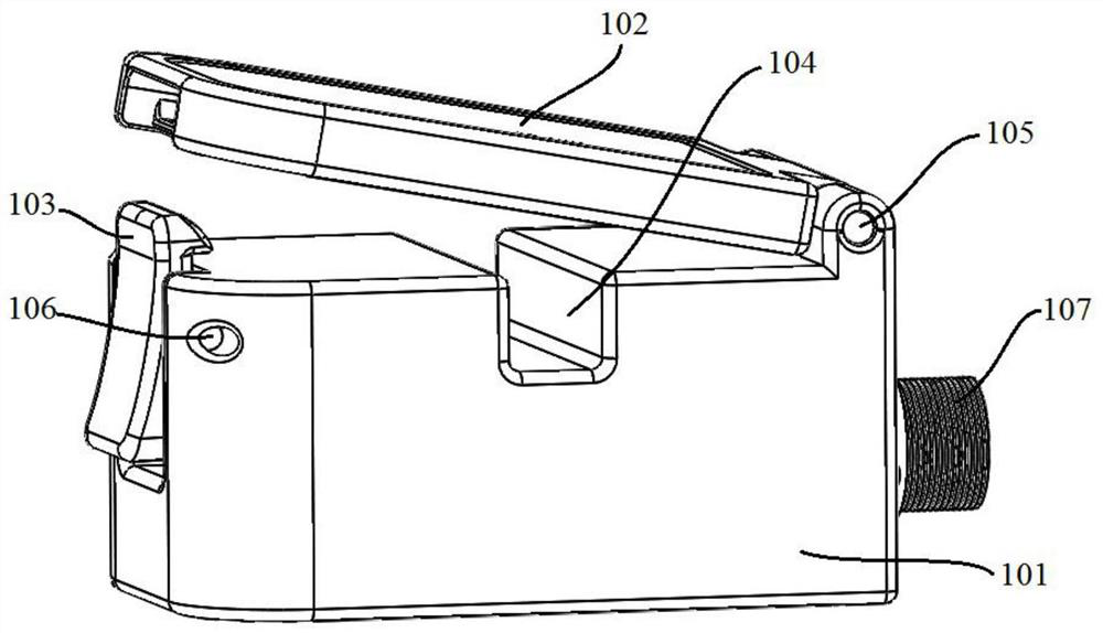
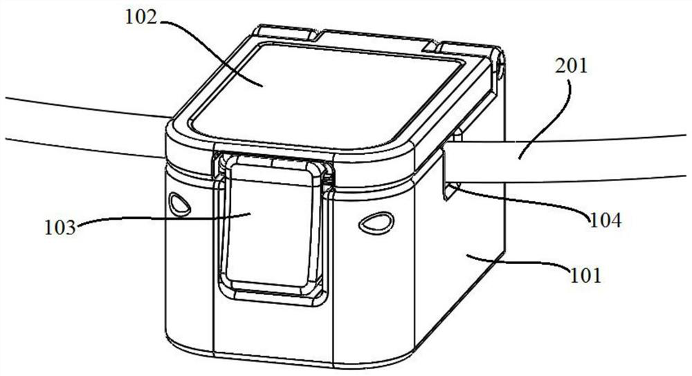
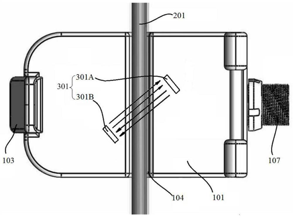
[0033] figure 1 It is a schematic structural diagram of the clip-on ultrasonic flow sensor provided in the first embodiment, figure 2 It is a schematic diagram of the structure of the clip-on ultrasonic flow sensor provided in the first embodiment after the hose is installed. image 3 It is a schematic diagram of the propagation direction of the ultrasonic signal in the clip-on ultrasonic flow sensor provided in the first embodiment, Figure 4 It is a schematic diagram of the installation structure of the ultrasonic transducer in the clip-on ultrasonic flow sensor provided in the first embodiment. This embodiment provides a clamp-type ultrasonic flow sensor, which is suitable for clamping small-diameter hoses, with simple operation, convenient installation, high measurement accuracy and low production cost, which includes: a housing, an upper cover, two Transducer, guided wave structure and ultrasonic flow measurement module.

[0034] Please refer to figure 1 , a groove i...

Embodiment 2

[0048] Figure 5 It is a schematic diagram of the guided wave structure in the clip-on ultrasonic flow sensor provided in the second embodiment, please refer to Figure 5 The difference between the second embodiment and the first embodiment is that the housing 101 of the ultrasonic flow sensor in this embodiment is a hollow structure, specifically, the area corresponding to the two side walls of the measurement channel 104 is not a solid structure. Between the measurement path 104 and the two ultrasonic transducers 301, a waveguide structure 501 is respectively arranged, the waveguide structure 501 is a solid structure, the waveguide structure 501 is a quadrilateral, and any side of the quadrilateral coincides with the side wall of the measurement path 104 ; The waveguide structure 501 can also be a triangle, and any side of the triangle coincides with the side wall of the measurement channel 104 . In this embodiment, the waveguide structure 501 is a right-angled trapezoid, a...

Embodiment 3

[0051] Figure 6 It is a schematic diagram of the guided wave structure in the clip-on ultrasonic flow sensor provided in Example 3, please refer to Figure 6 The difference between the third embodiment and the second embodiment lies in that the shape of the waveguide structure 501 is different.

[0052]Specifically, the width of the waveguide structure 501 in this embodiment gradually increases along the direction from the measurement passage 104 to the ultrasonic transducer 301, and the waveguide structure 501 is a quadrilateral, and any side of the quadrilateral is in contact with the side wall of the measurement passage 104 coincide. That is, the end of the waveguide structure 501 contacting the measurement channel 104 is narrow, and the end of the waveguide structure 501 contacting the ultrasonic transducer 301 is wide. The energy of pipelines and liquids is stronger, the received ultrasonic signal is stronger, and the signal-to-noise ratio is higher, which further impr...


PUM


Abstract

The invention provides a clamping type ultrasonic flow sensor. The sensor comprises a shell which is provided with a groove, and the first end of the shell is provided with a buckle; the sensor further comprises an upper cover, the first end of the upper cover is rotationally connected with the second end of the shell, the second end of the upper cover is buckled with the buckle and covers the groove, so that a measuring channel is formed, the measuring channel is used for containing a hose, and the width of the measuring channel is smaller than the pipe diameter of the hose in the natural state; the sensor further comprises two ultrasonic transducers which are both arranged on the face, different from the groove, of the shell and located on the two sides of the measuring channel respectively, the two ultrasonic transducers transmit and receive ultrasonic signals mutually, and an angle is formed between the propagation direction of the ultrasonic signals and the flowing direction of liquid in the hose. The problems that in the prior art, a clamping type ultrasonic flow sensor is difficult to clamp on a small-diameter hose, installation is difficult, the measuring precision is low, and the production cost is high are solved.

Description

technical field [0001] The invention relates to the technical field of ultrasonic measurement, in particular to a clip-type ultrasonic flow sensor. Background technique [0002] Ultrasonic flow sensors usually use the piezoelectric effect of piezoelectric materials, and use an appropriate transmitting circuit to add electrical energy to the piezoelectric element of the transmitting transducer to generate ultrasonic vibrations. Ultrasonic signals are injected into the fluid at a certain angle and propagated, then received by the receiving transducer, and converted into electrical energy by piezoelectric elements for detection. According to the principle of signal detection, the current ultrasonic flow sensor mainly adopts two types of time difference method and Doppler method. The Doppler method uses the principle of acoustic Doppler to determine the fluid flow rate by measuring the ultrasonic Doppler frequency shift scattered by the scattering body in the inhomogeneous flui...

Claims


Application Information

Patent Timeline
Patent Type & Authority Applications(China)
IPC IPC(8): G01F1/66G01F15/14G01F15/18
CPCG01F1/662G01F15/14G01F15/185
Inventor 沈西琳张宇明
Owner 上海迅音科技有限公司
Why Eureka
Try Eureka