
Single-mode optical fiber

a single-mode optical fiber and optical fiber technology, applied in the field of single-mode optical fiber, can solve the problems of unsuitability of conventional single-mode fiber (smf) specified in the international telecommunications, telecommunication standard sector (itu-t) g.652, and arise macro bending loss, so as to reduce the loss of splicing loss and macro bending loss, and achieve high-speed optical transmission

Inactive Publication Date: 2006-08-29
FURUKAWA ELECTRIC CO LTD
View PDF4 Cites 15 Cited by
  • Summary
  • Abstract
  • Description
  • Claims
  • Application Information

AI Technical Summary

Benefits of technology

[0022]This invention is made with the above view, and aims at realizing the reduction of both the macro bending loss and the splicing loss, and at providing a single-mode optical fiber which can perform high-speed optical transmission.

Problems solved by technology

If such demand is taken into consideration, the conventional single-mode fiber (SMF) specified in International Telecommunication Union Telecommunication Standard Sector (ITU-T) G.652 is unsuitable, since a large macro bending loss arises.
Generally, in the case of adding a bend to an optical fiber by external stress, the transmission loss of the optical fiber becomes large.
Additionally, with the optical fiber presented in the document cited above, the reduction of a macro bending loss at 1650 nm is still insufficient.
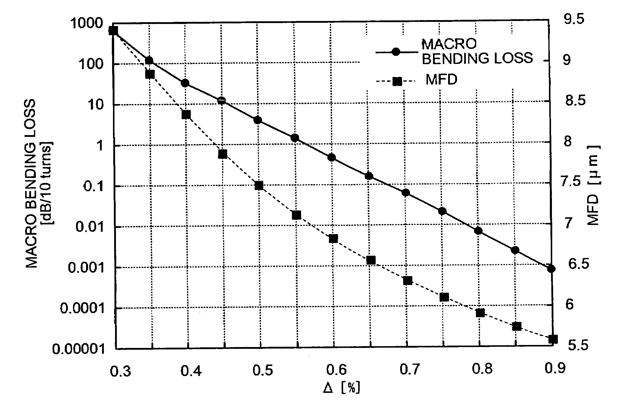
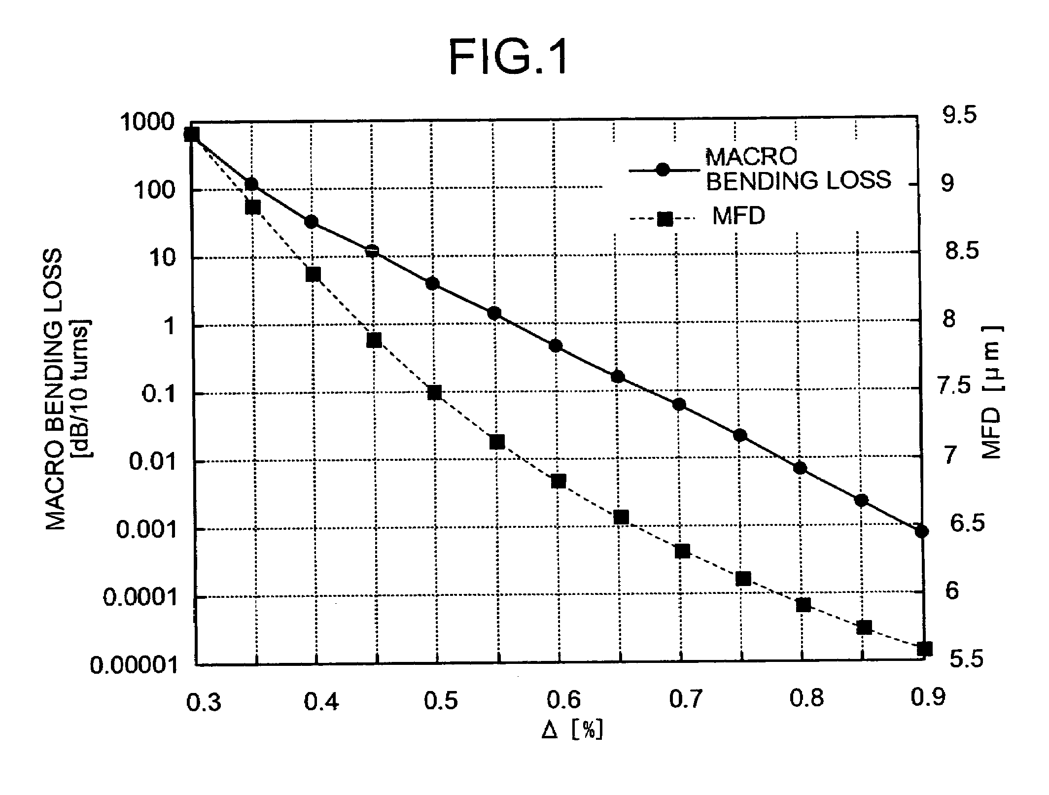
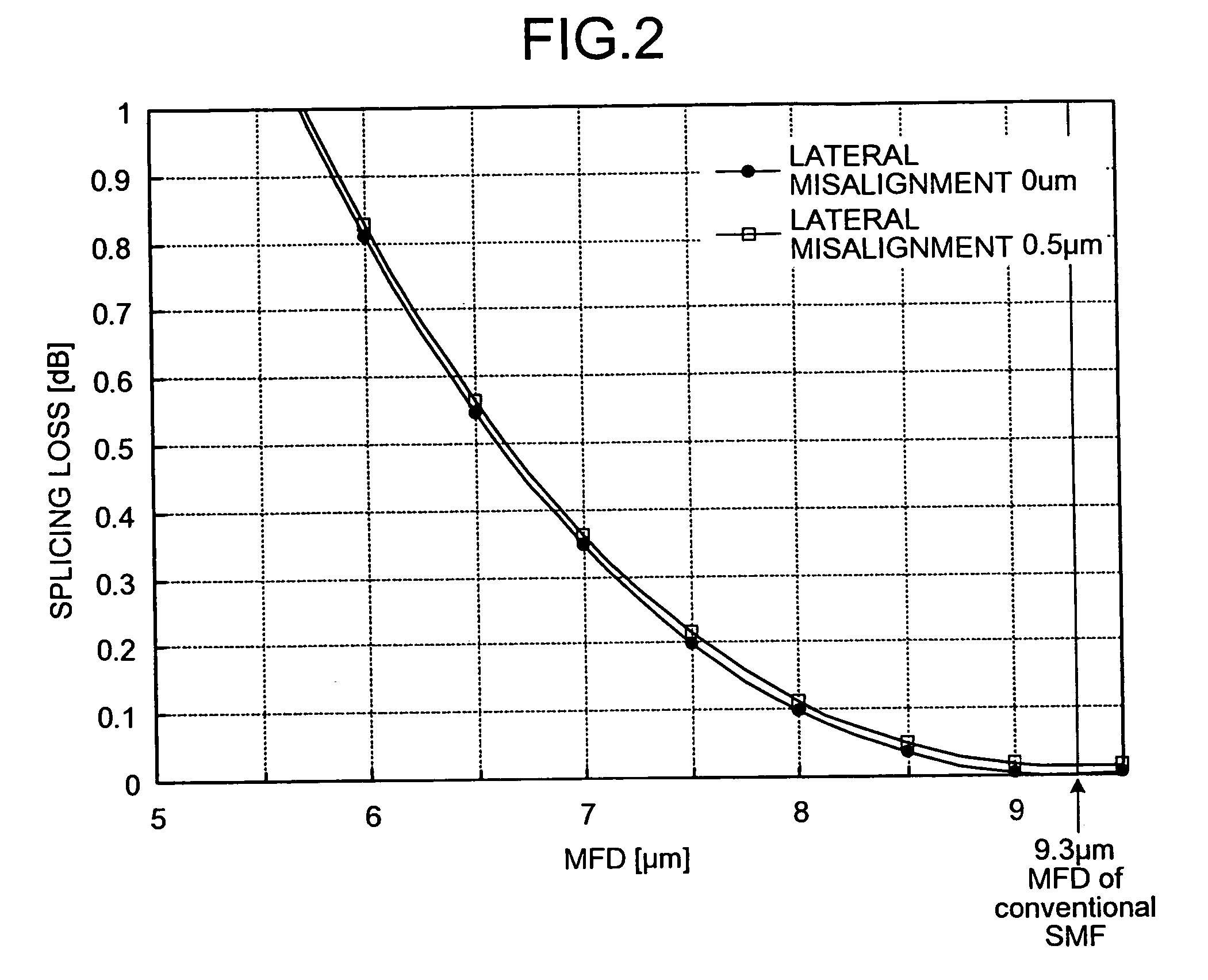
As above, in the design of the refractive index profile of optical fiber, if the relative refractive index difference Δ is made larger to reduce a macro bending loss, MFD becomes smaller, and it causes an increase in the splicing loss.

Method used


Image

  • Single-mode optical fiber
  • Single-mode optical fiber
  • Single-mode optical fiber

Examples


Embodiment Construction

[0034]Below, an embodiment of a single-mode optical fiber according to the invention will be described in detail with reference to drawings. However, the invention will not be limited by the embodiment of the invention. Below, the outline of characteristics of single-mode optical fiber's constitution related to the invention will be described as the embodiment, and then, actual single-mode optical fibers that meet such characteristics will be described in detail as examples of the embodiment.

[0035]The single-mode optical fiber of the embodiment improves a trade-off relation between the macro bending loss and the splicing loss by having a refractive index profile of the core area of a W-shaped profile of two-layer structure or a W segment shaped profile of three-layer structure, additionally optimizing the structural parameters thereof.

[0036]Here, the “W-shaped profile” is a refractive index profile shown in FIG. 5, and it means the profile which is a type of having a lower refractiv...


PUM

PropertyMeasurementUnit
wavelengthaaaaaaaaaa
mode field diameteraaaaaaaaaa

Abstract

Provided is a single-mode optical fiber that propagates an optical signal at a wavelength of 1310 nm, in single-mode operation; has a mode field diameter of 6.6 μm or more at the wavelength of 1310 nm; and a macro bending loss of at most 0.1 dB / 10 turns with a bending radius of 7.5 mm at a wavelength of 1650 nm.

Description

CROSS-REFERENCE TO RELATED APPLICATIONS[0001]This application claims the benefit of priority of Japanese Patent Application No. 2004-313625 filed on Oct. 28, 2004, and the disclosure of which is incorporated herein by its entirety.BACKGROUND OF THE INVENTION[0002]1) Field of the Invention[0003]This invention relates to a single-mode optical fiber that has a core and a cladding.[0004]2) Description of the Related Art[0005]There is a demand for more inexpensive ways to provide communication services, at various speeds, as a social infrastructure supporting the recent advanced information society, which is typified by Internet services. The introduction of optical fiber for offices and homes or apartments (FTTH: Fiber To The Home) is advancing at a rapid speed. With respect to optical fiber used for FTTH, just as with metal cables, ease of handling is required. That is, it is required that surplus cables are storable compactly in closures and cabinets; and that they are not damaged in ...

Claims


Application Information

Patent Timeline
Patent Type & Authority Patents(United States)
IPC IPC(8): G02B6/02G01J1/04G01N21/00G02B6/00
CPCG02B6/02009G02B6/03644G02B6/03627G02B6/0281
Inventor SAKO, AKIFUMISUGIZAKI, RYUICHIYAGI, TAKESHI
Owner FURUKAWA ELECTRIC CO LTD
Learn More