Free-space optical signal alignment and transmission device, system and method

Active Publication Date: 2020-06-25
HANGZHOU YAOXIN TECH CO LTD
View PDF0 Cites 6 Cited by
  • Summary
  • Abstract
  • Description
  • Claims
  • Application Information

AI Technical Summary

Benefits of technology

The present patent provides a solution for high-speed optical communication using a collimating lens module and an optical engine connected through a direct or optical fiber connection, eliminating the need for copper wires and back plates. This improves communication rate, reduces upgrade costs, and enables free-space optical communication. The disclosure integrates units for sending, alignment, transmission, and receiving of an optical signal, simplifying design and meeting different application requirements.

Problems solved by technology

As the transmission capacity increasingly grows in the communication field, it is difficult to meet the requirements in terms of the transmission capacity and transmission speed by means of the conventional transmission technologies.
In addition, as various intelligent terminals gain increasing improvement in their computing capacity, and become increasingly thin and portable, it is inconvenient for users to use the conventional cables for signal transmission.
Although radio signal transmission technology, such as WIFI and Bluetooth, can overcome such inconvenience to a certain degree, this technology has obvious limitations in high-speed signal transmission at present.

Method used


Image

  • Free-space optical signal alignment and transmission device, system and method
  • Free-space optical signal alignment and transmission device, system and method
  • Free-space optical signal alignment and transmission device, system and method

Examples


first embodiment

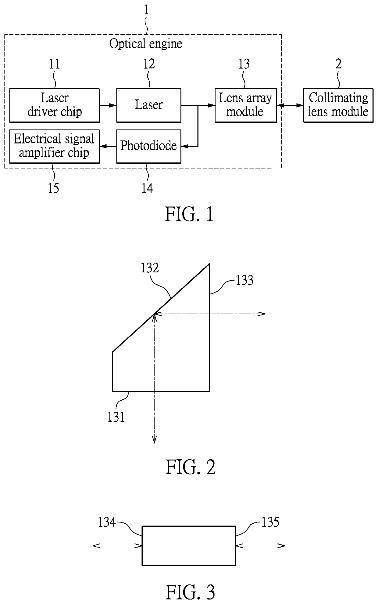
[0050]FIG. 1 is a first schematic structural diagram of a free-space optical signal alignment and transmission device provided by an embodiment of the present disclosure. As shown in FIG. 1, the free-space optical signal alignment and transmission device includes an optical engine 1 and a collimating lens module 2 which are directly connected.

[0051]During transmission of an optical signal, the optical engine 1 is configured to convert an electrical signal into an optical signal, and the collimating lens module 2 is configured to collimate the optical signal transmitted from the optical engine 1 and then send the collimated signal to free space for transmission. For receiving of the optical signal, the collimating lens module 2 is configured to shape the optical signal received from the free space and then send the shaped signal to the optical engine 1, and the optical engine 1 is configured to convert the optical signal into an electrical signal.

[0052]Specifically, the optical engin...

second embodiment

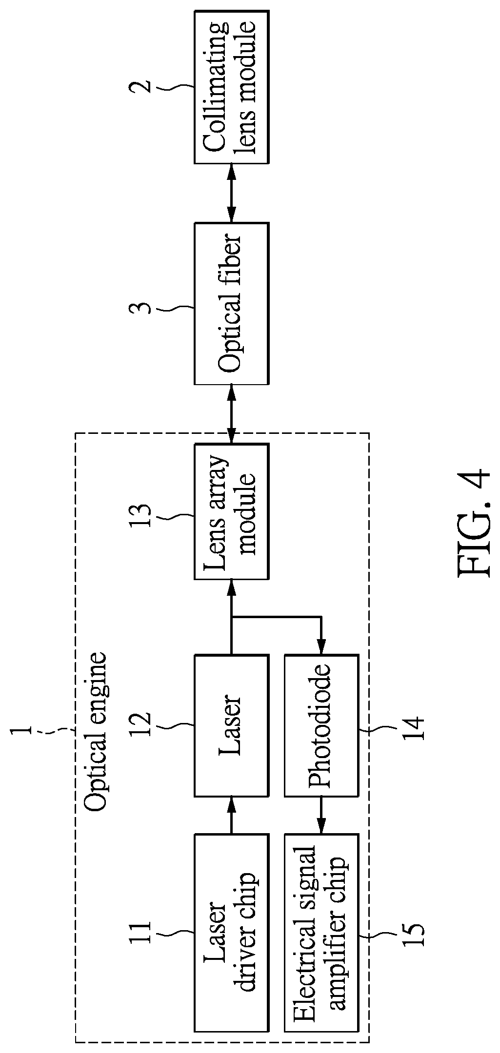
[0060]FIG. 4 is a second schematic structural diagram of a free-space optical signal alignment and transmission device provided by an embodiment of the present disclosure. As shown in FIG. 4, the free-space optical signal alignment and transmission device includes an optical engine 1, a collimating lens module 2, and an optical fiber 3. The optical engine 1 is connected to the collimating lens module 2 via the optical fiber 3.

[0061]During transmission of an optical signal, the optical engine 1 is configured to convert an electrical signal into an optical signal, the optical fiber 3 is configured for signal transmission, and the collimating lens module 2 is configured to collimate the optical signal transmitted from the optical fiber 3 and then send the collimated signal to free space for transmission. For receiving of the optical signal, the collimating lens module 2 is configured to shape the optical signal received from the free space, and then send the shaped signal to the optica...

third embodiment

[0068]Based on the foregoing first and second embodiments, the free-space optical signal alignment and transmission device further includes a WDM unit configured for combination and separation of optical wavelengths, which serves as an optical multiplexer during combination of the optical wavelengths and as an optical demultiplexer during separation of the optical wavelengths. During transmission of an optical signal, the WDM unit is configured to combine multiple paths of optical signals output by the optical engine 1 on one path for transmission. For receiving of the optical signal, the WDM unit is configured to split the received one path of optical signal into multiple paths for transmission.

[0069]Based on the foregoing first and second embodiments, the free-space optical signal alignment and transmission device further includes an alignment assembly which may be a locating pin or a locating hole and is provided on the base board. The alignment assembly can facilitate alignment ...


PUM


Abstract

Provided is a free-space optical signal alignment and transmission device, system, and method. The alignment and transmission device includes an optical engine and a collimating lens module which are connected. The optical engine converts an electrical signal into an optical signal and includes a base board, and a laser driver chip, a laser, a lens array module, a photodiode, and an electrical signal amplifier chip that are provided on the base board; the collimating lens module collimates and sends the optical signal transmitted from the optical engine to free space for transmission, and further shapes and sends the optical signal received from the free space to the optical engine. The laser is connected to the laser driver chip and the lens array module. One end of the photodiode is connected to the lens array module, and the other end thereof is connected to the electrical signal amplifier chip.

Description

FIELD OF THE DISCLOSURE[0001]The present disclosure relates to the field of information transmission technologies, and more particularly to a free-space optical signal alignment and transmission device, system and method.BACKGROUND OF THE DISCLOSURE[0002]As the transmission capacity increasingly grows in the communication field, it is difficult to meet the requirements in terms of the transmission capacity and transmission speed by means of the conventional transmission technologies. In addition, as various intelligent terminals gain increasing improvement in their computing capacity, and become increasingly thin and portable, it is inconvenient for users to use the conventional cables for signal transmission. Although radio signal transmission technology, such as WIFI and Bluetooth, can overcome such inconvenience to a certain degree, this technology has obvious limitations in high-speed signal transmission at present.SUMMARY OF THE DISCLOSURE[0003]To solve the problems in the prio...

Claims


Application Information

Patent Timeline
IPC IPC(8): H04B10/112G02B6/32H04B10/69G02B6/42H04B10/50
CPCG02B6/32H04B10/112H04B10/503G02B6/4204H04B10/69H04B10/11H04B10/40G02B27/30G02B27/1006
Inventor WANG, HAOWANG, DONG
Owner HANGZHOU YAOXIN TECH CO LTD
Why Eureka
Try Eureka