
Self-synchronization of an optical packet network using seed pulses extracted from within the packets

a packet network and packet technology, applied in the field of self-synchronization of an optical packet network, can solve the problems of not being able to provide optical processors capable of interpreting, unable to adequately accommodate timing jitters between transmitted optical packets, and unable to achieve the effect of converting to the electronic domain, which would defeat the advantage of using a high-speed optical network

Inactive Publication Date: 2006-08-29
UNIV OF MICHIGAN THE
View PDF3 Cites 7 Cited by
  • Summary
  • Abstract
  • Description
  • Claims
  • Application Information

AI Technical Summary

Benefits of technology

The present invention provides a way to synchronize an optical network without adding a separate marker to the data packet. Instead, the method uses one of the packet's own data pulses as a "seed" pulse for synchronization. This seed pulse remains the same as the other data pulses in the packet as it travels through the network. The method can be implemented using components inserted at nodes along the transmission pathway, rather than requiring special equipment at the signal generating or receiving stations.

Problems solved by technology

The technical problem addressed in this patent text is the need for a method and system for self-synchronization in a high-speed optical packet network that does not require appending marker pulses to the packets, is not susceptible to decay or disruption caused by propagation effects or intermediate components frequently encountered in existing transmission systems, does not unduly increase the complexity of the components required for signal generation and reception, and does not threatens the integrity of the transmitted data.

Method used


Image

  • Self-synchronization of an optical packet network using seed pulses extracted from within the packets
  • Self-synchronization of an optical packet network using seed pulses extracted from within the packets
  • Self-synchronization of an optical packet network using seed pulses extracted from within the packets

Examples


Embodiment Construction

[0034]Reference will now be made in detail to preferred embodiments of the present invention, examples of which are illustrated in the accompanying drawings. Wherever possible, the same reference numbers will be used throughout the drawings to refer to the same or like parts.

[0035]An exemplary embodiment of the method 10 of self-synchronizing an packet time-division multiplexed (TDM) optical network 12 of the present invention is shown in FIG. 1, and both the method and the associated system of this invention are designated generally throughout by that reference numeral 10.

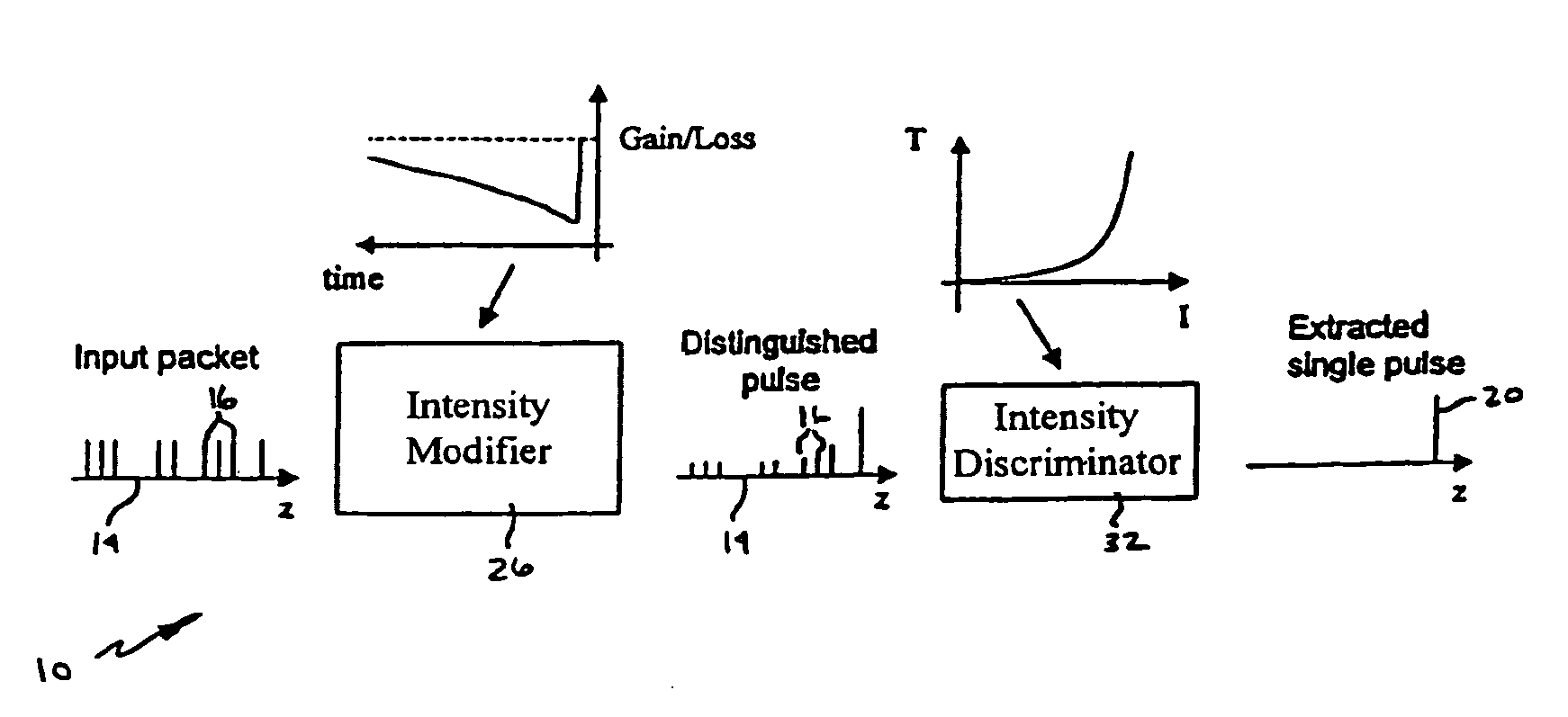
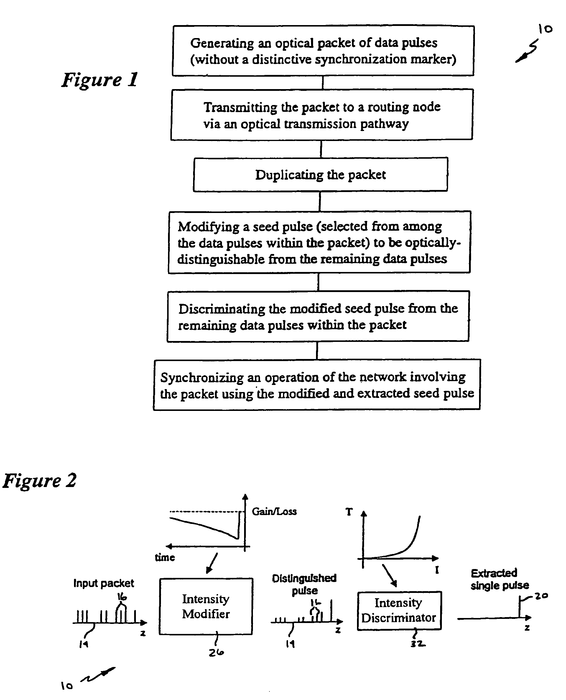
[0036]In accordance with the invention, referring particularly to FIG. 1, the method 10 of the present invention is practiced by generating a packet 14 including a plurality of data pulses 16 which omits or excludes a distinctive timing or synchronization marker that is optically distinguishable from the data pulses 16 in the packet 14, transmitting the packet 14 to a generally remote routing node 18 or other comp...


PUM


Abstract

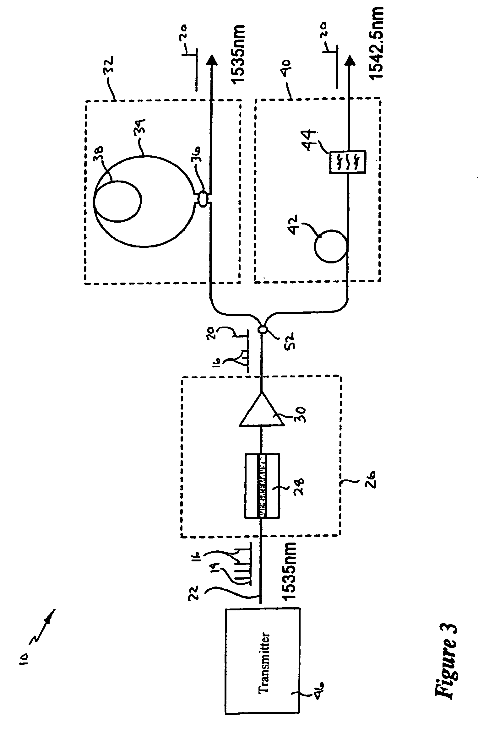
A method and system for self-synchronizing an optical packet network by selecting a seed pulse from among the data pulses within a packet having no synchronization marker, transforming the seed pulse to be optically distinguishable from the remaining data pulses after the packet has been transmitted, and extracting that seed pulse for use in synchronizing the operation of the network. In one embodiment, the process is practiced using a intensity modifier (such as a fast-saturation, slow-recovery amplifier) to modify the seed pulse intensity, and an intensity discriminator (such as an unbalanced NOLM, or a dispersion-shifted fiber and bandpass filter) to extract the differentiated seed pulse.

Description


Claims


Application Information

Patent Timeline
Owner UNIV OF MICHIGAN THE
Learn More