System and method for wireless data exchange between an appliance and a handheld device

a handheld device and wireless data technology, applied in the field of data communication, can solve problems such as the separation of leads from electronics, and achieve the effect of reducing the number of instances

Inactive Publication Date: 2006-08-29
GEBERIT INT AG
View PDF39 Cites 83 Cited by
  • Summary
  • Abstract
  • Description
  • Claims
  • Application Information

AI Technical Summary

Benefits of technology

[0021]An additional advantage of the present invention is provided by the cooperation of the anti-vandalism bracket and strain relief sheath of the present invention. The anti-vandalism bracket and strain relief sheath protect the electronics and the associated cables or leads providing a communication path between the dispensing apparatus and the electronics. In the past, separation of the leads from the electronics often resulted from individuals intentionally or otherwise pulling on the leads or associated connectors. In accordance with the present invention, these leads are now covered with a protective sheath that cooperates with the anti-vandalism bracket to withstand the pulling forces that would otherwise separate the leads from the electronics. The strain relief sheath may also provide a drip loop for capturing water that could otherwise damage the electronics, cable or connectors.
[0022]A further advantage to the present invention relates to the system's ability to control and manage any number of dispensing apparatuses from a central controller or computer. The preferred hubs used in the distributed network environment enable a plurality of dispensing apparatuses to be connected to a network via the standard RS232 serial ports provided with traditional electronically activated dispensing apparatuses presently available in the art. Moreover, the filtering and calibrating technology incorporated in the system of the present invention significantly limits the number of false detections and false activations, and therefore reduces the number of instances of dispensing apparatus malfunctions, wear and tear on the dispensing apparatuses, and the waste of fluids dispensed by such dispensing apparatuses.
[0023]Additional features and advantages of the invention will be set forth in the detailed description which follows and in part will be readily apparent to those skilled in the art from that description or recognized by practicing the invention as described herein.
[0024]It is to be understood that both the foregoing general description and the following detailed description are merely exemplary of the invention, and are intended to provide an overview or framework for understanding the nature and character of the invention as it is claimed. The accompanying drawings are included to provide further understanding of the invention, illustrate various embodiments of the invention, and together with the description serve to explain the principles and operation of the invention.

Problems solved by technology

In the past, separation of the leads from the electronics often resulted from individuals intentionally or otherwise pulling on the leads or associated connectors.

Method used


Image

  • System and method for wireless data exchange between an appliance and a handheld device
  • System and method for wireless data exchange between an appliance and a handheld device
  • System and method for wireless data exchange between an appliance and a handheld device

Examples


Embodiment Construction

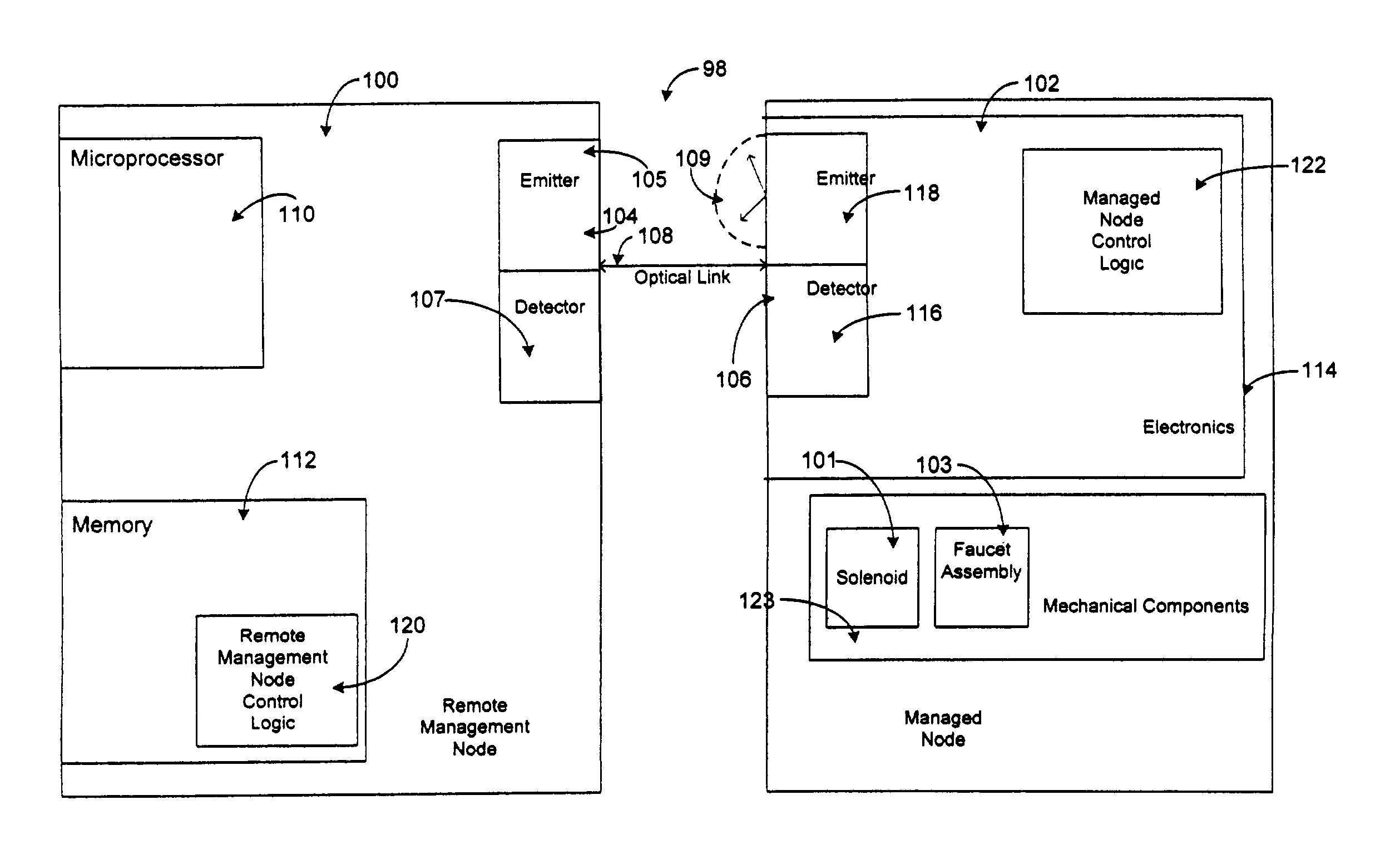
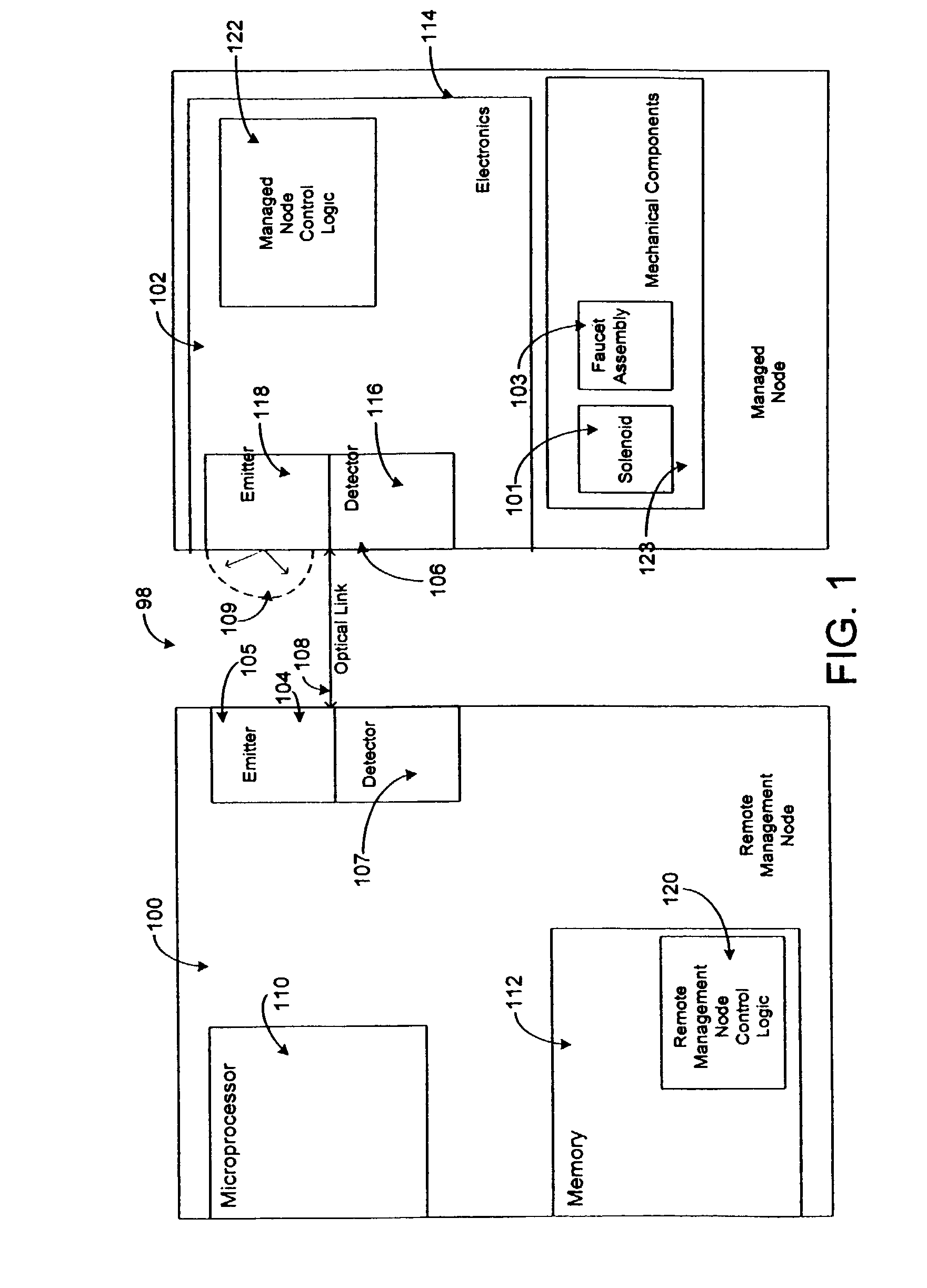
[0057]Reference is now made in detail to a present preferred embodiments of the present invention, examples of which are illustrated in the accompanying drawings. Wherever possible, the same reference numerals will be used throughout the drawing figures to refer to the same or like parts. An exemplary embodiment of the data communication system and method of the present invention is illustrated in the block diagram of FIG. 1 and is designated generally throughout by reference numeral 98.

[0058]In accordance with the invention, the hardware elements of one preferred embodiment of the data communication system of the present invention include Remote Management Node 100 and Managed Node 102. Remote Management Node 100 includes generally an optical interface port 104, a processing element 110, and a memory element 112. Managed Node 102 includes generally an optical interface port 106, an electronics module 114, and a Mechanical Element 123. The optical interface port 106 of Managed Node ...


PUM


Abstract

A wireless data exchange system is disclosed. The system includes an electronically operated appliance including a transmitter, a receiver, and a control module configured to communicate with the transmitter and receiver. The control module provides a primary mode of operation and a secondary mode of operation and includes control logic configured to selectively change the mode of operation of the electronically operated appliance. A communication device adapted to be held in the hand of a user is configured to cooperate with the transmitter and the receiver to impart instructions wirelessly to the control logic in order to change the mode of operation of the electronically operated appliance upon receipt of a command from a user. A method of exchanging data wirelessly between an apparatus and a communication device is also disclosed.

Description

CROSS-REFERENCE TO RELATED APPLICATIONS[0001]This application claims the benefit of priority under 35 U.S.C. § 119(a) of U.S. Provisional Patent Application Ser. No. 60 / 267,441 entitled, “Remotely Managed Automatic Dispensing Apparatus and Method”, filed on Feb. 8, 2001, and U.S. Provisional Patent Application Ser. No. 60 / 242,898 entitled, “Remotely Managed Automatic Dispensing Apparatus and Method”, filed on Oct. 24, 2000, both of which are incorporated herein by reference in their entireties.BACKGROUND OF INVENTION[0002]1. Field of the Invention[0003]The present invention relates generally to the field wireless data communications, and more particularly, to data communication between a handheld device having an optical interface port that transmits and receives signals with an optical interface port of an electronically operated appliance.[0004]2. Technical Background[0005]Standard infrared (IR) devices communicate in accordance with the Infrared Data Association Serial Infrared P...

Claims


Application Information

Patent Timeline
Patent Type & Authority Patents(United States)
IPC IPC(8): H04B1/06G05B19/00G07F9/02G07F13/02G07F13/06G08C23/04H04B10/08H04B10/10
CPCG05B19/00G06Q20/327G07F9/026G07F13/025G07F13/06H04B10/1143G08C23/04H04B10/07H04B10/114G07F13/065G08C2201/42G08C2201/51G07F9/001
Inventor PATTERSON, WADE C.WATSON, THOMAS J.
Owner GEBERIT INT AG
Why Eureka
Try Eureka