Point and adapter assembly

a technology of adapter and wear parts, applied in the field of wear parts, can solve the problems of ejection of the member, exacerbate the difficulty of resisting high ejection force, wear parts are subjected to high abrasion conditions, etc., and achieve the effect of reducing frictional force, reducing wear, and improving resistance to ejection

Inactive Publication Date: 2006-09-05
ESCO GRP LLC
View PDF68 Cites 115 Cited by
  • Summary
  • Abstract
  • Description
  • Claims
  • Application Information

AI Technical Summary

Benefits of technology

[0015]The present invention pertains to a wear assembly that provides a stable coupling which is able to resist heavy loading without placing undue stress on the lock.
[0017]In another aspect of the invention, the wear member rotates on and off of the adapter about its longitudinal axis to better resist ejection forces. In a preferred embodiment, the rotation is accomplished with generally linear rails and grooves that are easy and inexpensive to manufacture. These complementary rails and grooves enable the assembly to have a more slender profile than otherwise possible with helical threads for better penetration in excavation uses and less use of metal. Such grooves and rails also avoid the generation of high stress risers due to the use of relatively sharp grooves used to form helical threads.
[0019]In another aspect of the invention, the adapter includes two bearing surfaces positioned on opposite sides of the longitudinal axis and facing in opposite directions. In a preferred embodiment, these bearing surfaces reduce wear on the extreme fibers on the top and bottom of the nose. Moreover, the bearing surfaces are preferably formed as part of rails on the adapter so as to form a generally Z-shaped cross-section.
[0020]In another aspect of the invention, the adapter nose and socket of the wear member widen as they extend forwardly. In a preferred embodiment, the adapter and socket include complementary rails and grooves that diverge to require twisting of the wear member during installation. This construction provides sufficient clearance to receive the forwardly widened nose into the socket to better resist ejection of the wear member.
[0021]In another aspect of the invention, the lock is tapered to fit into a complementary channel to reduce frictional forces and ease the insertion and removal of the lock. In this configuration, the length of the lock does not frictionally slide through aligned openings, but rather engages the sides of the channel at or near the place of engagement. Hammering of the lock as it is inserted or removed is avoided. In a preferred embodiment, the lock includes a lock member to secure the lock in the channel to prevent unwanted loss or ejection.

Problems solved by technology

Accordingly, the wear parts are subjected to highly abrasive conditions and experience considerable wearing.
Vertical loads have been particularly troublesome in that large moment forces are generated that tend to “rotate” the wear members forward on the adapter and at times result in the ejection of the member.
Moreover, the impacts, vibration, wear, and presence of fines, etc. exacerbate the difficulty of resisting high ejection forces.
The repeated application of high shear loads can place unacceptably high stresses on the lock pin and result in its breakage.
Further, in such conventional teeth, the lock pin is typically hammered into place and tightly held by frictional forces applied primarily by the placement of the holes in the point relative to the hole in the adapter nose.
However, wearing of the point and adapter will tend to loosen the connection and increase the risk of losing the lock pin.
This can be a troublesome and time-consuming task, especially in the larger sized teeth.
While the elastomer functions to pull the point onto the adapter, it also reduces the lock's ability to resist the applied moment and reverse forces.
These loads tend to place more stress on the elastomer than it can withstand.
As a result, during use, overworking of the elastomer can result in its premature failure and loss of the lock pin, which then results in loss of the point.
The loss of a point due to pin failure, looseness or elastomer problems not only results in premature loss of the point and wearing of the adapter nose, but also in possible damage to machinery that may be processing the excavated material, particularly in a mining operation.
Moreover, since the adapter is often welded in place, replacement of an adapter usually results in significant down time for the digging equipment.
While this design improves the stability of the point over the conventional tooth system, it still applies a substantial ejection force and can place high shear forces on the lock.
While this construction provides great strength and retention benefits, the nose and socket are complex and more expensive to manufacture.

Method used


Image

  • Point and adapter assembly
  • Point and adapter assembly
  • Point and adapter assembly

Examples


Embodiment Construction

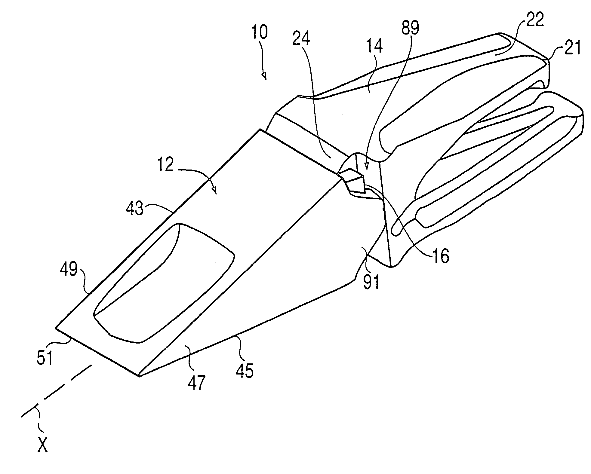
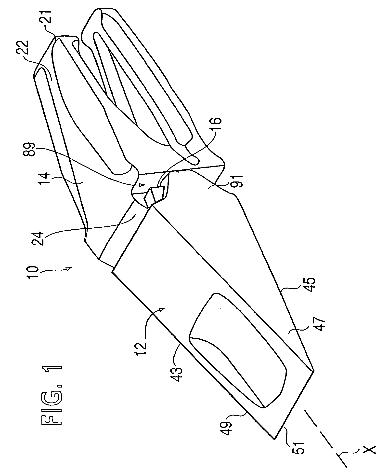
[0050]The present invention is directed to a wear assembly for protecting a wear surface. In particular, the wear assembly is especially adapted for use in excavating, mining, construction and the like. The wear assembly is well suited for use in forming an excavating tooth system, but could also be used to form other wear members.

[0051]For purposes of illustration, the present application describes the inventive construction as an excavating tooth system. The production of other wear parts (e.g., a shroud) would utilize the same nose and socket constructions, but could have different working and mounting ends. For the sake of description only, terms such as upper, lower, vertical, etc. are used in this specification and are to be understood as pertaining to the tooth system as oriented in FIG. 1. The use of these terms is not an indication that these particular orientations are required for the wear assembly. The wear assembly could be oriented differently than as illustrated in FI...


PUM


Abstract

A wear assembly including an adapter, a wear member, and a lock to secure the wear member to the adapter, wherein the adapter and wear member include at least one rail and corresponding groove along the nose and socket connection that are oriented at the same general inclination as one of the converging walls of the nose.

Description

[0001]This application is a continuation of U.S. patent application Ser. No. 09 / 899,535 filed Jul. 6, 2001, which is now U.S. Pat. No. 6,735,890.FIELD OF THE INVENTION[0002]The present invention pertains to a wear assembly, and especially to a wear assembly for use with mining, excavating and earthmoving equipment. The inventive design is particularly well suited for an excavating tooth, but may also be used for the support of other wear members.BACKGROUND OF THE INVENTION[0003]In mining and construction, wear members are typically provided along the digging edge of the equipment to protect the bucket or the like and / or to engage and break up the ground to be gathered. Accordingly, the wear parts are subjected to highly abrasive conditions and experience considerable wearing. The wear parts must then be replaced on a periodic basis.[0004]In order to minimize the loss of material due to replacement of worn parts, the wear assemblies are typically manufactured as two or more separable...

Claims


Application Information

Patent Timeline
Patent Type & Authority Patents(United States)
IPC IPC(8): E02F9/28
CPCE02F9/28E02F9/2825E02F9/2833E02F9/2883E21C35/183E02F9/2841Y10T403/7018Y10T403/587F16B2200/71
Inventor CARPENTER, CHRISTOPHER M.FLECK, ROBERT S.BRISCOE, TERRY L.DANKS, DANIEL R.GAURAV, VENKAT R.JONES, LARREN F.
Owner ESCO GRP LLC
Why Eureka
Try Eureka