Wheel assembly including a DC motor mounted within the HUB and drive connected to the wheel

a technology of dc motor and hub, which is applied in the direction of propulsion parts, transportation and packaging, electric propulsion mounting, etc., can solve the problems of large, heavy, labor-intensive motor, and complex system, and achieve the effect of improving speed and better control

Inactive Publication Date: 2006-09-05
PEERLESS WINSMITH
View PDF17 Cites 41 Cited by
  • Summary
  • Abstract
  • Description
  • Claims
  • Application Information

AI Technical Summary

Benefits of technology

[0006]Accordingly, the primary object of this invention is to provide a novel modular wheel drive assembly which includes a unique lightweight, compact DC motor mounted within the hub of the assembly.
[0009]A further object of the invention is to provide the above assembly wherein the motor is a separately excited shunt wound DC motor used with an electronic controller to provide more speed and better control.

Problems solved by technology

These systems tend to be mechanically complicated and expensive and utilize space on the vehicle which could be more efficiently occupied by other components.
Various type wheel assemblies which include conventional AC or DC electric motors and planetary speed reducer units to drive the wheel have also been previously proposed, but those assemblies have not been widely accepted commercially.
The result was a large, heavy, very costly, labor intensive motor which did not lend itself for application for use in a wheel assembly.

Method used


Image

  • Wheel assembly including a DC motor mounted within the HUB and drive connected to the wheel
  • Wheel assembly including a DC motor mounted within the HUB and drive connected to the wheel
  • Wheel assembly including a DC motor mounted within the HUB and drive connected to the wheel

Examples


Embodiment Construction

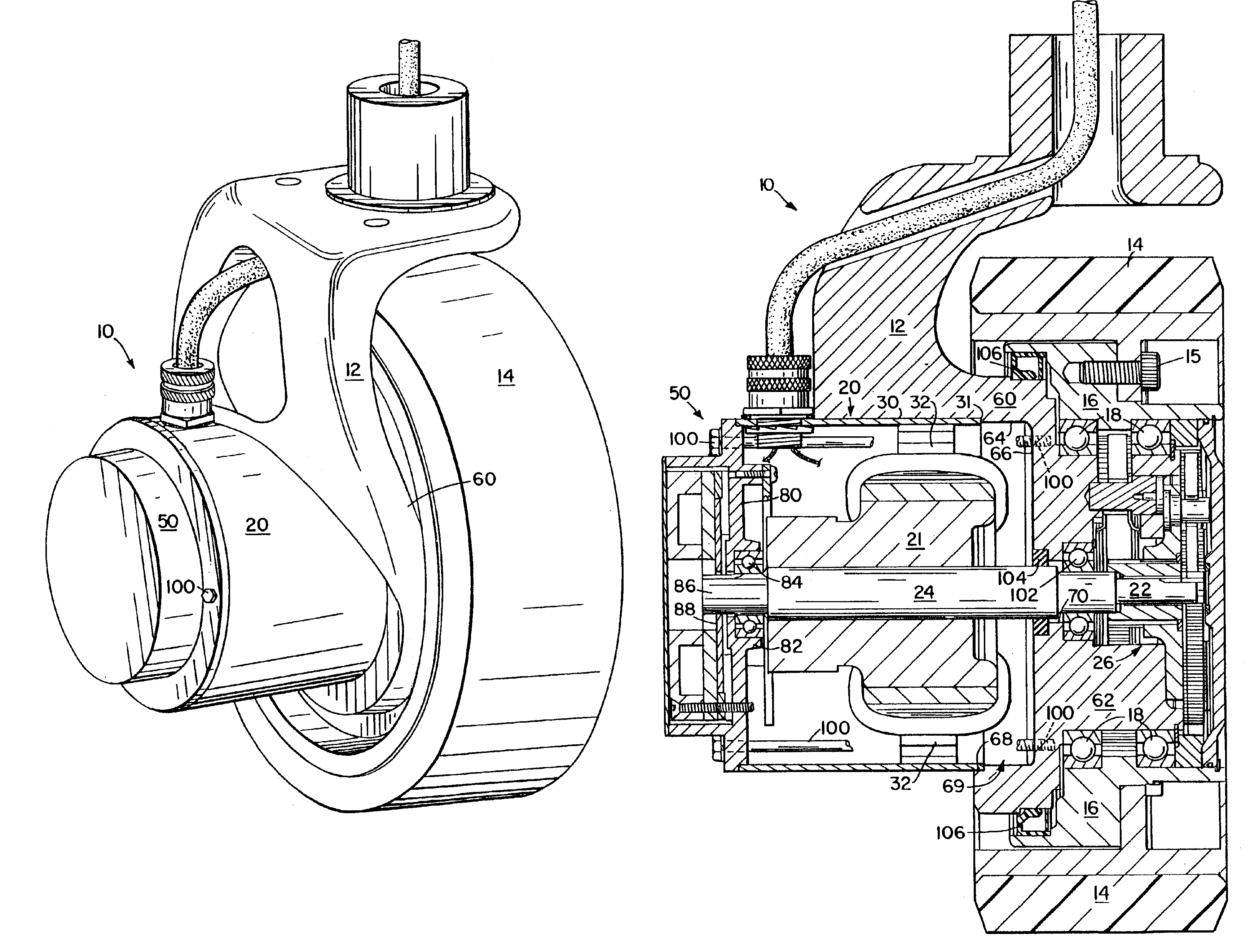
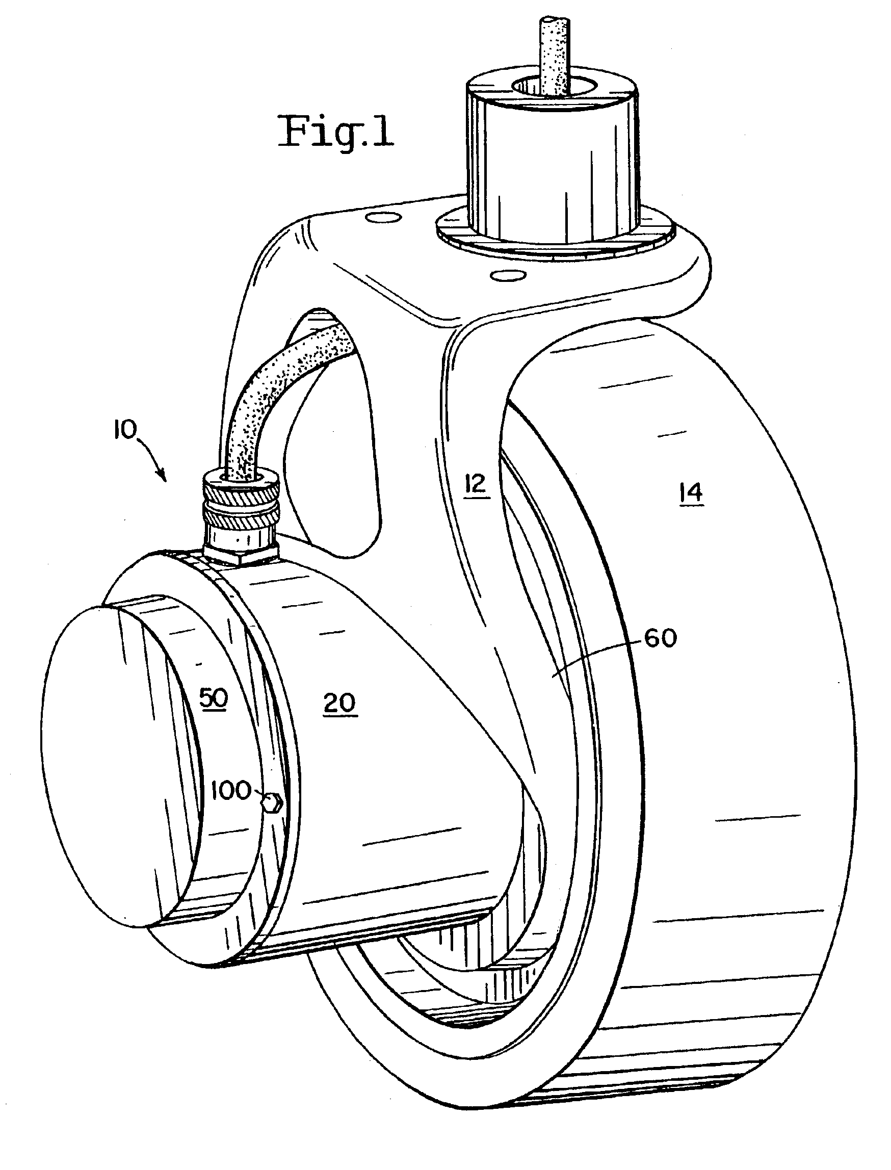
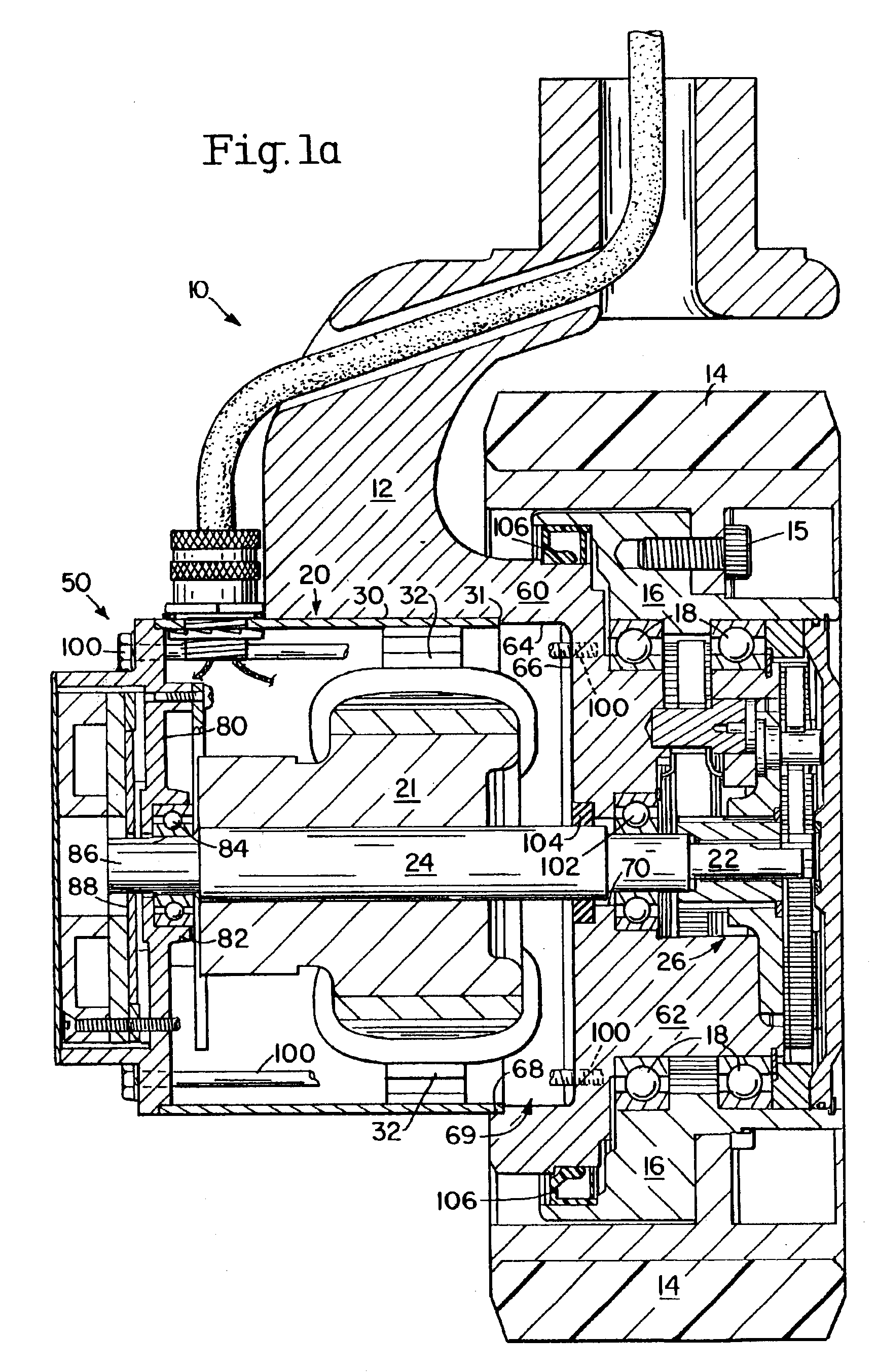
[0021]Referring now to the drawings, wheel assembly 10 includes a hub 12 having a first cylindrical outer section 60 and a second reduced diameter cylindrical inner section 62. Section 60 has an inner bore 64, an end wall 66, and a larger outer counterbore 68. Bore 64, end wall 66, and counterbore 68 define a chamber 69. A smaller stepped central bore 70 extends through wall 66 and inner section 62. A wheel 14 (about 12″-18″ in diameter) is fastened via cap screws 15 to a ring 16 which is rotatably mounted via bearings 18 on the outer diameter of hub section 62.

[0022]A separately excited shunt wound DC motor 20 is mounted within chamber 69 of hub section 60 and includes a rotatable armature 21 having coils 23 and a shaft 24 whose inner drive end 22 is drive connected to the sun gear of a planetary speed reducer assembly 26 which rotates ring 16 and wheel 14 when motor 20 is energized. Planetary assembly 26 is fastened to hub section 62.

[0023]The separately excited shunt wound motor ...


PUM


Abstract

A modular, self-driven vehicle wheel assembly including a drive motor carried by the wheel assembly. The assembly includes a hub, a wheel rotatably mounted on the hub, and a planetary speed-reducing unit mounted on the hub and drivingly connected with the wheel. The drive motor is a shunt wound DC motor that is coaxially mounted adjacent to the wheel and within a chamber formed in the hub. The motor is drivingly connected with the planetary speed-reducing unit to transmit motor torque to rotate the wheel in either a forward direction or a reverse direction. A brake assembly is carried adjacent to the motor for selectively applying a braking force to brake the motor armature when the wheel is to remain in a stationary condition.

Description

RELATED APPLICATIONS[0001]This application is a continuation-in-part of copending provisional application Ser. No. 60 / 406,692, filed on Aug. 29, 2002, the disclosure of which is incorporated herein by reference in its entirety, the benefit of its earlier filing date being hereby claimed according to 37 C.F.R. §1.78(4).BACKGROUND OF THE INVENTION[0002]The present invention relates to a wheel assembly for use in vehicles such as a scissor lift and more particularly relates to a modular wheel assembly which includes a wound field DC motor mounted within the hub of the assembly and directly driving the wheel via an intermediate planetary gear mechanism.[0003]In the past, the wheels of such vehicles have been driven primarily by external hydraulic motor systems connected to the wheels by intermediate adapter components. These systems tend to be mechanically complicated and expensive and utilize space on the vehicle which could be more efficiently occupied by other components. Various typ...

Claims


Application Information

Patent Timeline
Patent Type & Authority Patents(United States)
IPC IPC(8): B60K1/00B60K7/00B60K17/04H02P7/298
CPCB60K7/0007H02P7/298B60K17/046B60K2007/0092
Inventor BOWEN, DALE R.
Owner PEERLESS WINSMITH
Why Eureka
Try Eureka