Light assembly

a technology of light assembly and light beam, which is applied in the direction of lighting and heating equipment, lighting support devices, and with built-in power, etc., can solve the problems of insufficient clear view and shadows that plague home craftsmen or repairmen

Inactive Publication Date: 2006-09-05
ROBERT BOSCH GMBH +1
View PDF22 Cites 35 Cited by
  • Summary
  • Abstract
  • Description
  • Claims
  • Application Information

AI Technical Summary

Benefits of technology

[0012]One benefit of the present invention is that it provides a light attachment that can be attached to a variety of tools or fixtures or other support structures to provide direct illumination where it is needed most. Another benefit is that the light emitting portion is carried by a flexible cable that allows positioning the light in an infinite number of positions.
[0013]A further benef

Problems solved by technology

However, a clear view may be insufficient if the workpiece is not adequately illuminated.
E

Method used


Image

  • Light assembly
  • Light assembly
  • Light assembly

Examples


Embodiment Construction

[0026]For the purposes of promoting an understanding of the principles of the present invention, reference will now be made to the embodiments illustrated in the drawings and described in the following written specification. It is understood that no limitation of the scope of the invention is thereby intended. It is further understood that the present invention includes any alterations and modifications to the illustrated embodiments and includes further applications of the principles of the invention as would normally occur to one skilled in the art to which this invention pertains.

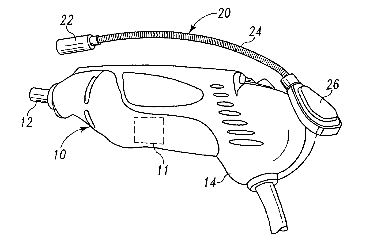
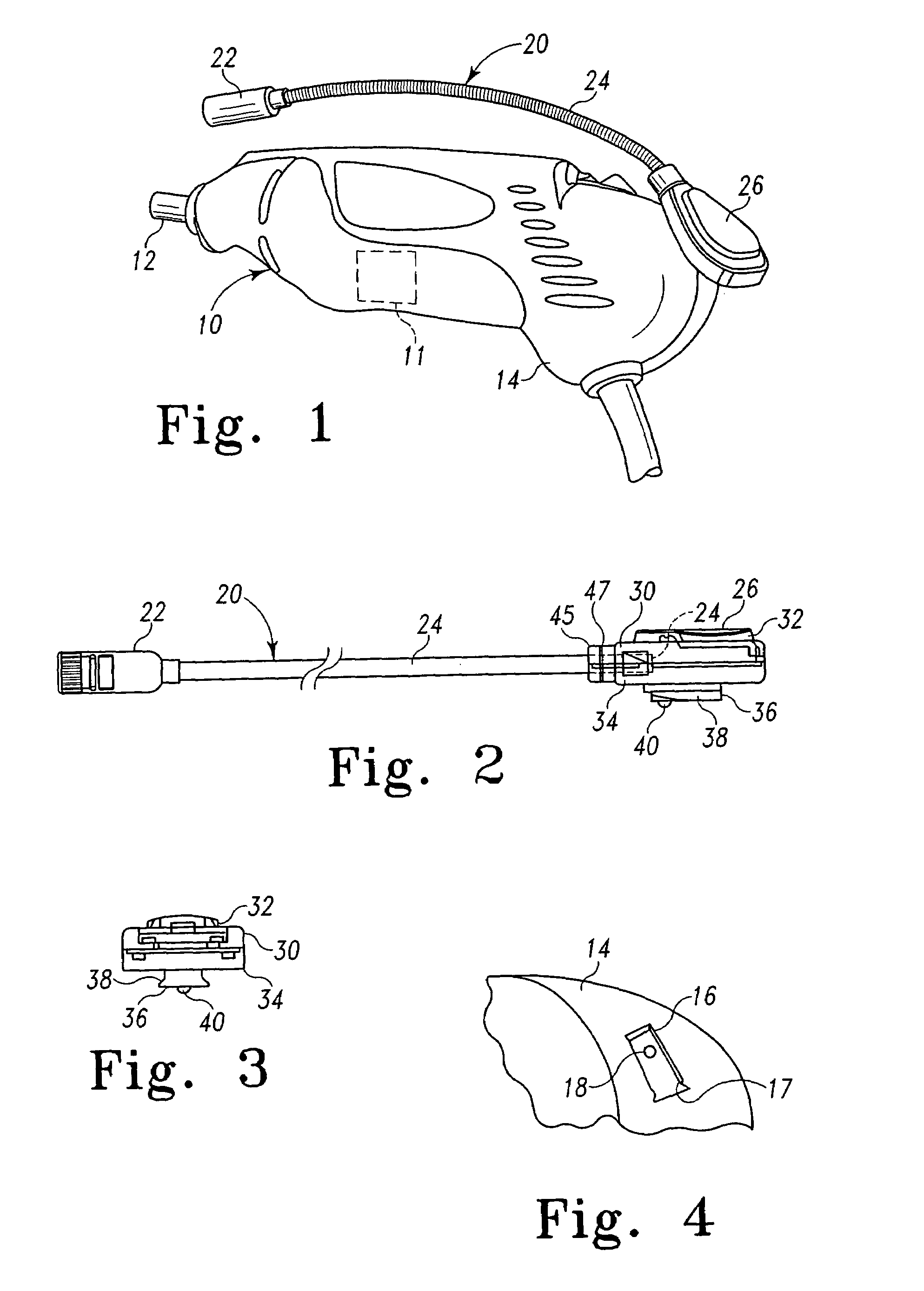
[0027]The present invention is particularly suited for use with a hand-held tool, such as a rotary hand-held power tool 10 shown in FIG. 1. The power tool 10 includes a working end 12 that can be a collet for attachment of various rotary tool bits, such as bits for grinding, sharpening, routing, cutting, carving, engraving, cleaning, polishing, and sanding. The tool 10 includes a body 14 that houses driv...


PUM


Abstract

A light attachment that can be readily mounted on a variety of tools and tool support fixtures and other support structures includes a light portion supported on a mounting portion by a flexible gooseneck cable. The mounting portion includes a housing that defines a male-female attachment element configured to slidingly mate with a complementary attachment element formed on the body of the power tool. In a preferred embodiment, the attachment element has a dovetail shape for sliding engagement within a complementary shaped notch in the body of the tool. The housing contains a power source for the light portion. The light portion incorporates an on-off switch that is actuated by rotating a component that is threadedly engaged within the housing. The housing supports a printed circuit board to which the power supply wires are attached. The circuit board also carries a spring contact switch element that completes an electrical circuit to energize the light portion when the spring contact is pressed against the circuit board. Power is supplied through the circuit board and switch to an LED light element. The LED is disposed within the housing so that the rotatable component can push the base of the LED into the spring switch to close the electrical circuit.

Description

[0001]This application is a continuation-in-part of both (i) co-pending application Ser. No. 10 / 680,513, filed on Oct. 7, 2003, and (ii) co-pending application Ser. No. 10 / 680,632, filed on Oct. 7, 2003. The disclosure of each of the above-identified utility patent applications is hereby totally incorporated by reference in its entirety.[0002]Also, this application claims the benefit of U.S. Provisional Application Ser. No. 60 / 509,360, filed Oct. 7, 2003. The disclosure of this provisional patent application is hereby totally incorporated by reference in its entirety.BACKGROUND OF THE INVENTION[0003]The present invention relates to a light assembly, and particularly to devices for shedding light on a workpiece during operation of a power tool, such as a hand-held rotary power tool.[0004]Hand-held power tools have been used by individuals for many decades. Such individuals include craftsman, repairman, hobbyists, and woodworkers to name a few. From the day that the power drill replac...

Claims


Application Information

Patent Timeline
IPC IPC(8): F21V33/00B25F5/02B27C5/10B27C9/00F21L4/06F21S9/02F21V21/088F21V21/32
CPCB25F5/021B25F5/029B27C5/10B27C9/005F21V21/088F21V33/0084F21Y2101/02F21S9/02F21V21/32F21L4/06F21Y2115/10
Inventor PRELL, EDWARD T.BABER, BRAD M.LEUNG, FRANKIEALLEMANN, MARKUSBERNARDI, WALTER
Owner ROBERT BOSCH GMBH
Why Eureka
Try Eureka