Cutting tool and cutting head thereto

a cutting tool and cutting head technology, applied in the field of cutting tools and cutting heads thereto, can solve the problems of cutting head, obvious disadvantage, no indexing,

Inactive Publication Date: 2006-09-05
SANDVIK INTELLECTUAL PROPERTY AB
View PDF23 Cites 46 Cited by
  • Summary
  • Abstract
  • Description
  • Claims
  • Application Information

AI Technical Summary

Benefits of technology

[0004]A primary object of the present invention is to provide a rotary tool of the type defined in the introduction, which has a good stability in spite of the fact that the cutting head is dismountable.
[0006]Another object of the present invention is that an indexing between the cutting head and the shaft of the tool in the direction of rotation of the tool should be possible.

Problems solved by technology

It can not be understood from WO 02 / 05996 that there is any indexing between the cutting head and the shaft of the tool, which seems obvious since the presence of the thread couplings in principle makes indexing impossible.
However, no indexing takes place in the direction of rotation of the cutting head, which is an obvious disadvantage.

Method used


Image

  • Cutting tool and cutting head thereto
  • Cutting tool and cutting head thereto
  • Cutting tool and cutting head thereto

Examples


Embodiment Construction

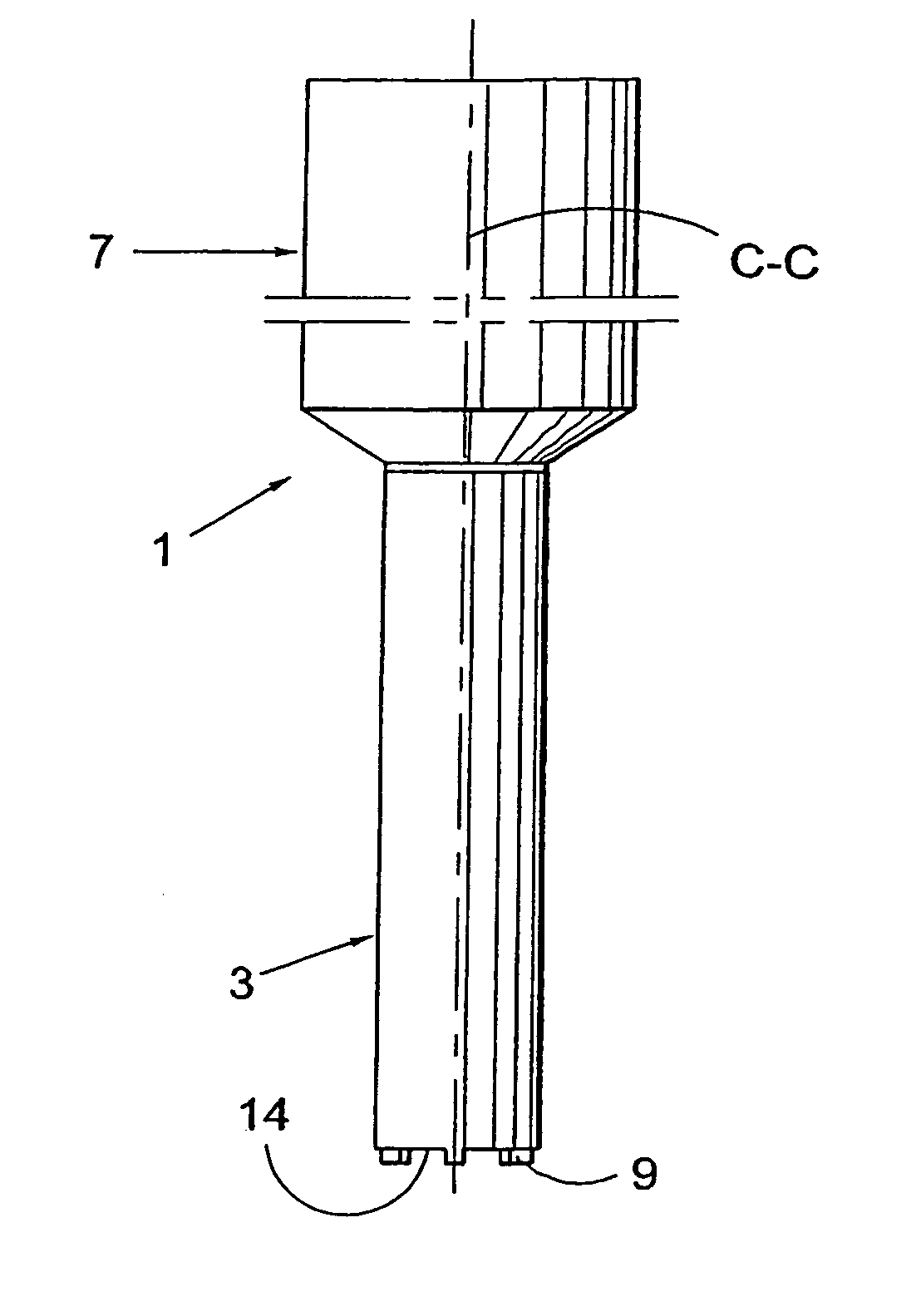
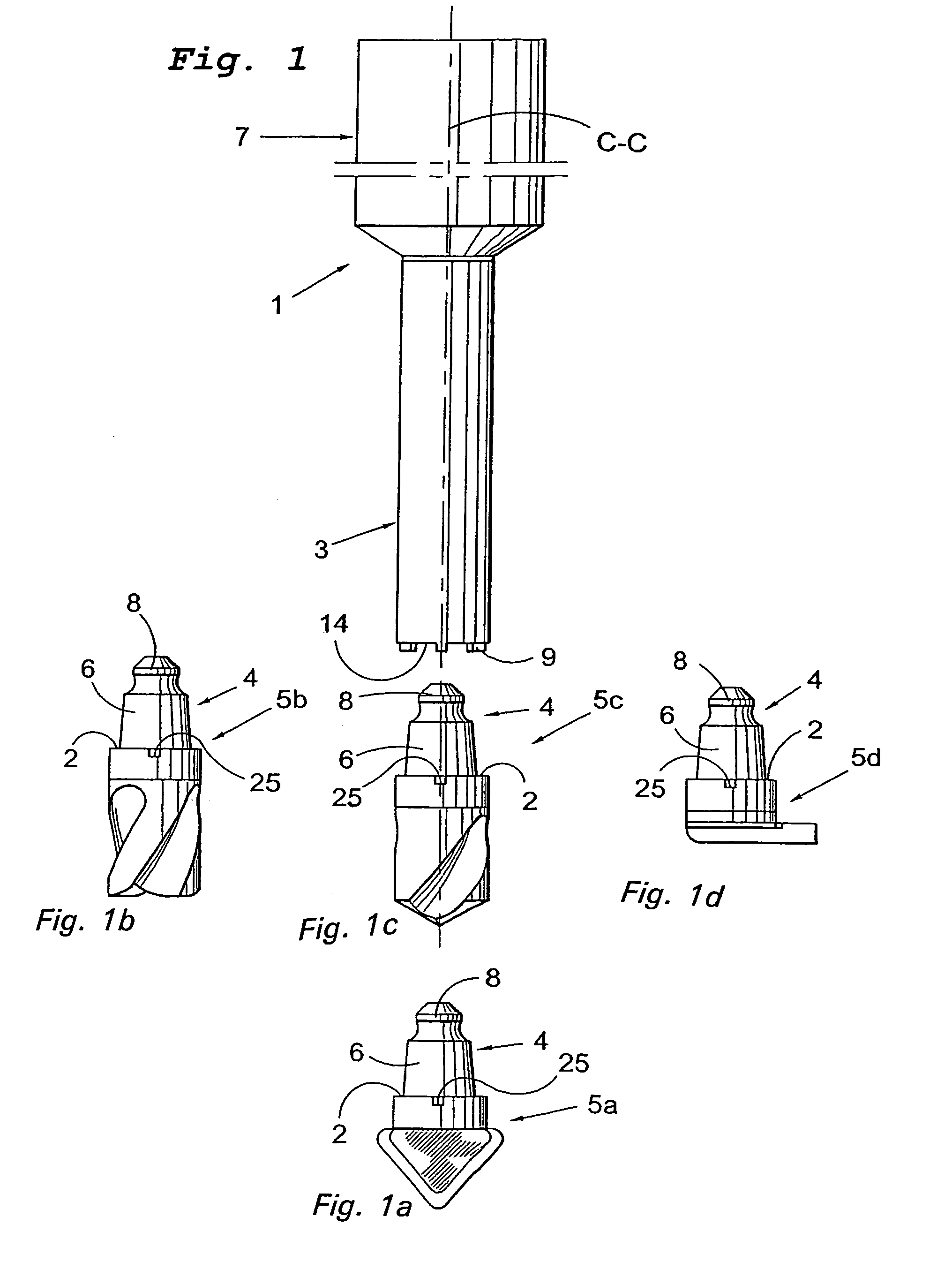
[0019]The shaft of the tool 1, illustrated in FIGS. 1 and 2, comprises a holder part 3 for receipt of a cutting head 5a–5d as well as a clamping part 7, which is intended to be clamped in a machine tool. In FIG. 1, a longitudinal centre axis C—C is drawn in, thus extending in the axial direction of the tool shaft 1.

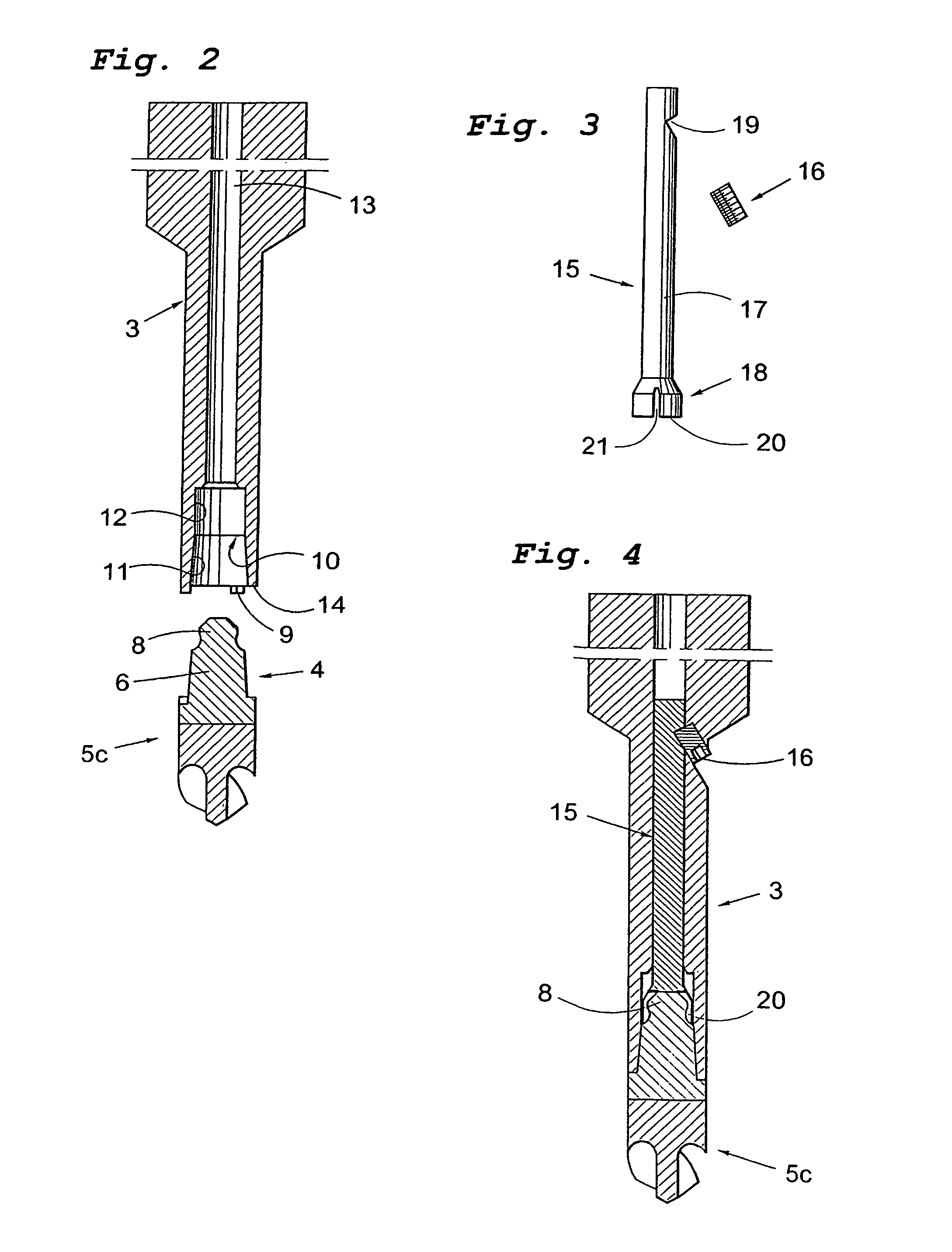
[0020]In the shaft of the tool 1 according to FIGS. 1 and 2, the holder part 3 is externally circular cylindrical and at the free end thereof, the holder part 3 has a number of rigid projections or shoulders 9, which have an extension both in the axial direction C—C of the tool shaft and in the direction of the circumference of the holder part 3. Between the rigid shoulders 9, the holder part 3 has a stop face 14. As is seen in FIG. 2, the shaft of the tool 1 is, at the free end of the holder part 3, provided with a recess forming an internal seat 10, which in the illustrated embodiment is divided into a conical female part 11, situated closest to the free end of the hold...


PUM

PropertyMeasurementUnit
flexibleaaaaaaaaaa
axial rearward forceaaaaaaaaaa
forceaaaaaaaaaa

Abstract

A tool such as a milling or drilling tool includes a shaft having a front recess in which a cutting head is disposed. A drawbar disposed in the shaft includes a plurality of flexible tongues disposed in the recess. The tongues form a recess in which a rear knob of the cutting head is received. A retainer urges the drawbar axially rearwardly to retain the cutting head in the recess. The shaft includes axial projections at its front end which are received in respective rearwardly open recesses of the cutting head to prevent relative rotation between the shaft and the cutting head.

Description

TECHNICAL FIELD OF THE INVENTION[0001]The present invention relates to a tool, especially for chip removing machining, whereby the tool, for instance, consists of a milling cutter or a drill. The tool comprises a tool shaft having a seat arranged in the shaft of the tool (which seat is located adjacent to one end of the shaft of the tool), a cutting head intended to be mounted in the seat, a drawbar (whereby the cutting head and the drawbar have members for interconnection), as well as members for applying a force to the drawbar in the axial direction of the tool shaft. The invention also separately relates to a cutting head that constitutes a replaceable part of the tool according to the present invention.PRIOR ART[0002]A tool unit is previously known from WO 02 / 05996, which comprises a cutting head, a tool shaft, as well as an elongated drawbar, which is axially displaceable in a hole of the shaft of the tool. The cutting head is connected to the drawbar via a thread coupling and ...

Claims


Application Information

Patent Timeline
Patent Type & Authority Patents(United States)
IPC IPC(8): B23C5/26B23Q11/00B23B29/04B23B31/26
CPCB23B29/046B23B31/261Y10T407/192Y10T409/309464Y10T409/30952Y10T408/95Y10T408/957Y10T409/309408
Inventor HANSSON, PER
Owner SANDVIK INTELLECTUAL PROPERTY AB
Why Eureka
Try Eureka