Attachment system

a technology of clamping connection and clamping rod, which is applied in the direction of threaded fasteners, rod connections, screws, etc., can solve the problems of axial displacement of the to-be-clamped parts, e.g. rod movement, and the inability to precisely adjust the height of the aligned rod member, so as to facilitate cam sliding and prevent the self-release of the clamping connection

Inactive Publication Date: 2006-09-05
HILTI AG
View PDF61 Cites 15 Cited by
  • Summary
  • Abstract
  • Description
  • Claims
  • Application Information

AI Technical Summary

Benefits of technology

[0022]The curved profile can be formed as toothing, with separate intervening elements being provided with different inclinations. The length of the displacement path for effecting locking, e.g., for displacement of the engagement means of the receiving sleeve from the first position to the second position, is determined by the inclination angle. For compensation of the thread tolerances between the rod member, when it is formed as a threaded rod, and the engagement means of the receiving sleeve and for locking of the rod member, a flatter inclination adjoins a more steep inclination. With a flatter inclination, the necessary clamping force is applied, and a self-release of the clamping connection is prevented by self-locking of the connection.
[0023]According to an alternative embodiment of the present invention, the curved profile is formed by cams which engage in indentations and / or recesses and which are withdrawn from the recesses and / or indentations upon actuation of the actuation member. After being withdrawn, the cams slides over a corresponding surface of the constructional component or of the stop. When, e.g., the cams are provided in the actuation member, the constructional component or stop is provided with complementary indentations and / or recesses. The indentation and / or recesses have, preferably, inclinations in the displacement direction of the actuation member which facilitate sliding of the cams out of the indentations and / or recesses upon actuation of the actuation member. In this way, with this embodiment of the curved profile, an axial displacement of the actuation member takes place upon its actuation, and the engagement means is displaced from the first position to the second position.
[0024]Advantageously, the adjusting surface of the receiving sleeve and / or the actuation surface of the actuation member is formed as an ascending surface and / or sloping surface and, optionally, as a spiral surface. The advantage of ascending or sloping surface consists in that the inclination can be varied along its extent. E.g., the adjusting surface of the receiving sleeve can have a predetermined inclination and be formed in a region of the receiving sleeve. The actuation member, e.g., can have an actuation surface that engages the adjusting surface or covers it. The actuation surface can have, at its beginning, a greater inclination which provides for engagement of the engagement means of the receiving sleeve with the rod member at a smaller displacement of the actuation member. A surface with a smaller inclination can adjoin the surface with a grater inclination of the actuation member. The surface with a smaller inclination provides for securing of the rod member by the attachment system. The ascending and / or sloping is preferably formed with a continuously varying inclination, with the surface having a spiral shape.

Problems solved by technology

The drawback of the attachment system, with which clamping is used, consists in that during the clamping process, an axial displacement of the to-be-clamped parts, e.g., of the threaded rod takes place.
As a result of the axial displacement, no precise height adjustment of the aligned rod member is possible and, therefore, of the conduit that is attached thereto.

Method used


Image

  • Attachment system
  • Attachment system
  • Attachment system

Examples


first embodiment

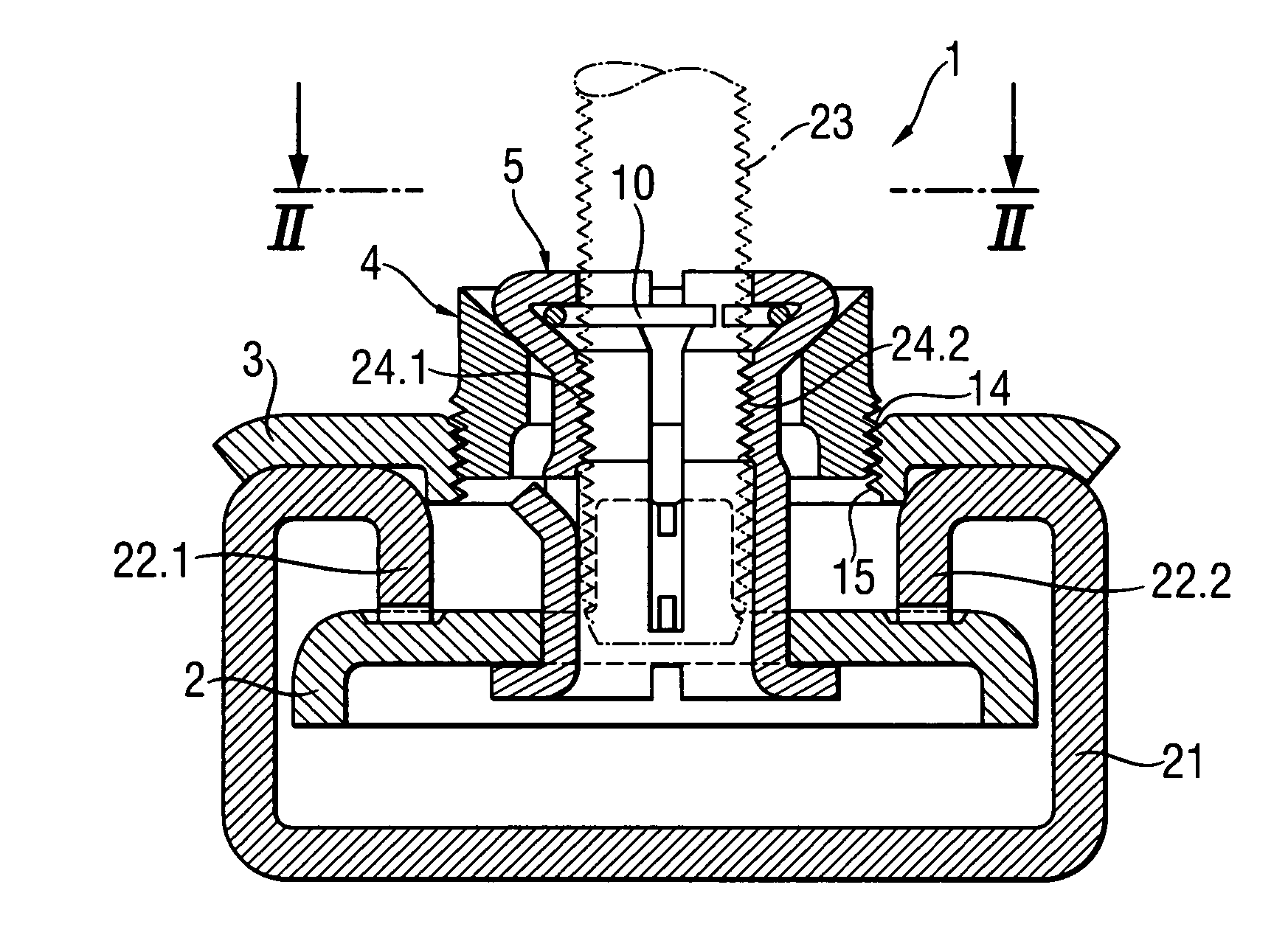
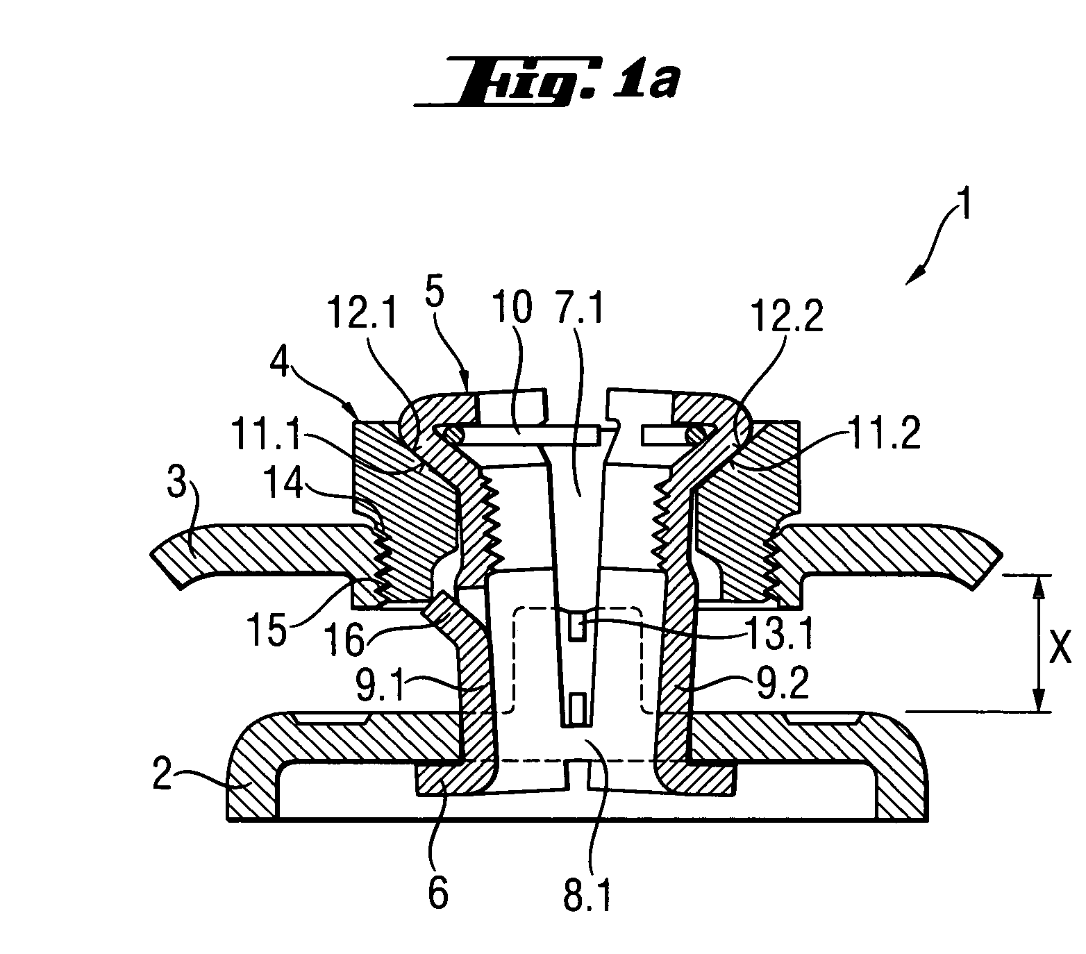
[0047]FIG. 1a, as discussed above, shows an attachment system according to the present invention in its open position, i.e., in a position for receiving a rod member. In its setting direction, the inventive attachment system includes a rear engagement member 2 and a receiving sleeve 5 that engages the rear engagement member 2 from behind. At the end of the attachment system 1 remote from the rear engagement member 2, there are provided a stop 3 and an actuation member 4.

[0048]The receiving sleeve 5 ahs a flange 6 with which it engages the rear engagement member 2. The flange 6 is secured to the rear engagement member 2 with a sealing lacquer or a solder. The receiving sleeve 5 is formed as a one-piece part of a sheet metal and has two opposite slots 7.4 and 7.2 that extend from the end of the attachment system 1 remote from the rear engagement member 2 to an opposite end of the attachment system 1. At the end of the receiving sleeve 5 facing in the setting direction of the attachmen...

third embodiment

[0059]FIG. 6 shows a cross-sectional view of the attachment system 61 according to the present invention in its closed or locking position. An actuation member 62 of the attachment system 61 has a curved profile that engages in a complementary curved profile provided on a stop 63. Upon actuation of the actuation member 62, it slides over the stop 63 and is lifted off the stop 63, and due to the engagement of the receiving sleeve 64 with the actuation member 62, the threaded section 69.1 and 69.2 of the receiving sleeve 64 are displaced from their first, open position into their second, locking position.

[0060]The receiving sleeve 64, which is shown in FIG. 6, is formed of two sections 65.1 and 65.2. The sections 65.1 and 65.2 are resiliently connected with each other at their ends facing in the setting direction of the attachment system, with overlapping sections 66.1 and 66.2 which are soldered with each other. The separate sections 65.1 and 65.2 of the receiving sleeve 64 are conne...


PUM


Abstract

An attachment system for securing a rod member in a mounting opening of a constructional component (44; 74; 97) includes a receiving sleeve (5; 37; 64; 73; 93) for receiving the rod member (23; 40), and an actuation member (4; 35; 62; 72; 81; 92) connected with the receiving sleeve (5; 37; 64; 73; 93) for substantially radially displacing the engagement elements (24.1; 24.2; 49.1; 49.1; 69.1; 69.2; 98.1; 98.2) of the receiving sleeve, which engage the rod member, from a first position in which the rod member is received in the receiving sleeve (5; 37; 64; 73; 93) to a second position in which the rod member is locked in the receiving sleeve.

Description

BACKGROUND OF THE INVENTION[0001]1. Field of the Invention[0002]The present invention relates to an attachment system for securing a rod member in a mounting opening of a constructional component, in particular, for securing a threaded rod in a mounting opening of a hollow body, and including a receiving sleeve for receiving the rod member and having engagement means for engaging the rod member.[0003]2. Description of the Prior Art[0004]Attachment systems of the type described above are used, e.g., in suspending devices for conduit installations such as tubular conduits and the like, for attachment to so-called mounting rails. A threaded rod with a pipe clip and, if necessary, with a tubular conduit already mounted in the clip is prepositioned with the attachment system on a mounting rail. Then, the threaded rod is height-adjusted and is secured with a rail nut and / or lock nut. The end attachment should be backlash-free so that the attachment system can withstand high loads.[0005]Th...

Claims


Application Information

Patent Timeline
Patent Type & Authority Patents(United States)
IPC IPC(8): F16B27/00F16B37/04F16B37/08
CPCF16B37/045F16B37/0864Y10T403/7067Y10T403/4674F16B2200/40
Inventor HERB, ARMIN
Owner HILTI AG
Why Eureka
Try Eureka