
Weight exercise device

a weight exercise and body technology, applied in the field of body exercise equipment, can solve the problems of body injury or property damage, varies the degree of resistance of the trainee, and the danger of falling or being dropped, so as to achieve uniform resistance

Inactive Publication Date: 2006-09-05
CARLE JOHN T
View PDF20 Cites 34 Cited by
  • Summary
  • Abstract
  • Description
  • Claims
  • Application Information

AI Technical Summary

Benefits of technology

[0008]It is, therefore, an object of the invention to provide a weight exercise device upon which a weight lifting trainee can perform a substantial variety of standard weight lifting exercises and experience substantially uniform resistance throughout the range of motion of each exercise.
[0009]A further object is to provide such a device that is compact and conveniently stores its weights when the weights are not in use and in a way that does not interfere with any exercise movements.

Problems solved by technology

Bar bells and dumbbells, however, can inadvertently fall or be dropped, possibly resulting in bodily injury or property damage; and, the danger of their falling or being dropped is higher when used by new and unconditioned weight trainees.
These and similar weight training devices of the prior art provide a body-engaging means attached to a first end of a pivot arm or lever, means for pivoting the lever, and weight resistance means attached to a second, opposite end of the lever, with the result that, as a weight trainee moves the body-engaging means through the range of motion of a selected weight lifting exercise, the degree of resistance the trainee experiences varies through the range of motion of the exercise, and generally not in any optimal way.
The exercise devices of Mahnke and of Koenig do not satisfactorily solve the problem presented, however.
Moreover, the devices of Mahnke and Koenig can only be used for a relatively few kinds of weight lifting exercises; they are not suitable, for example, for triceps extensions or arm curls.

Method used


Image

  • Weight exercise device
  • Weight exercise device
  • Weight exercise device

Examples


first embodiment

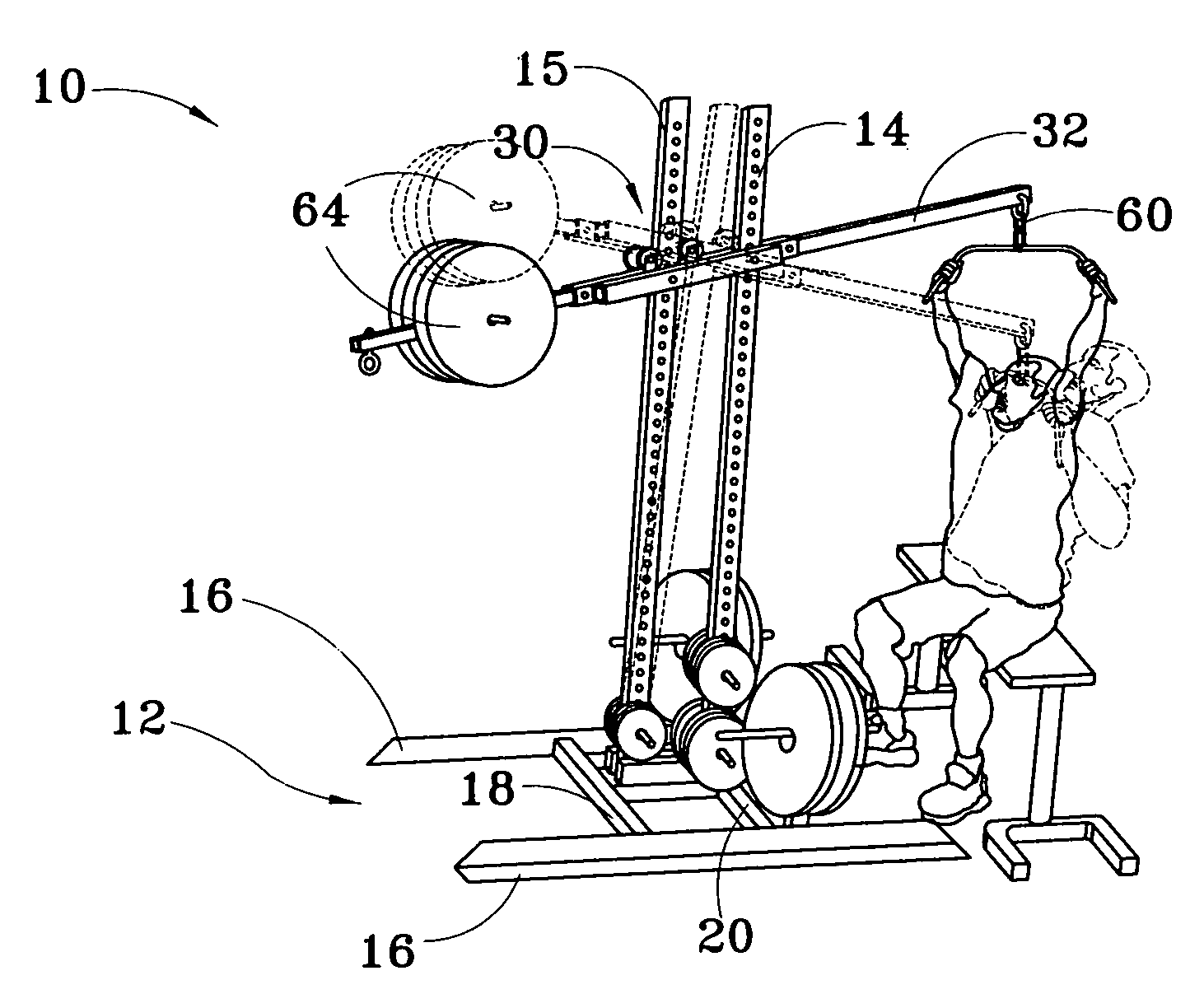
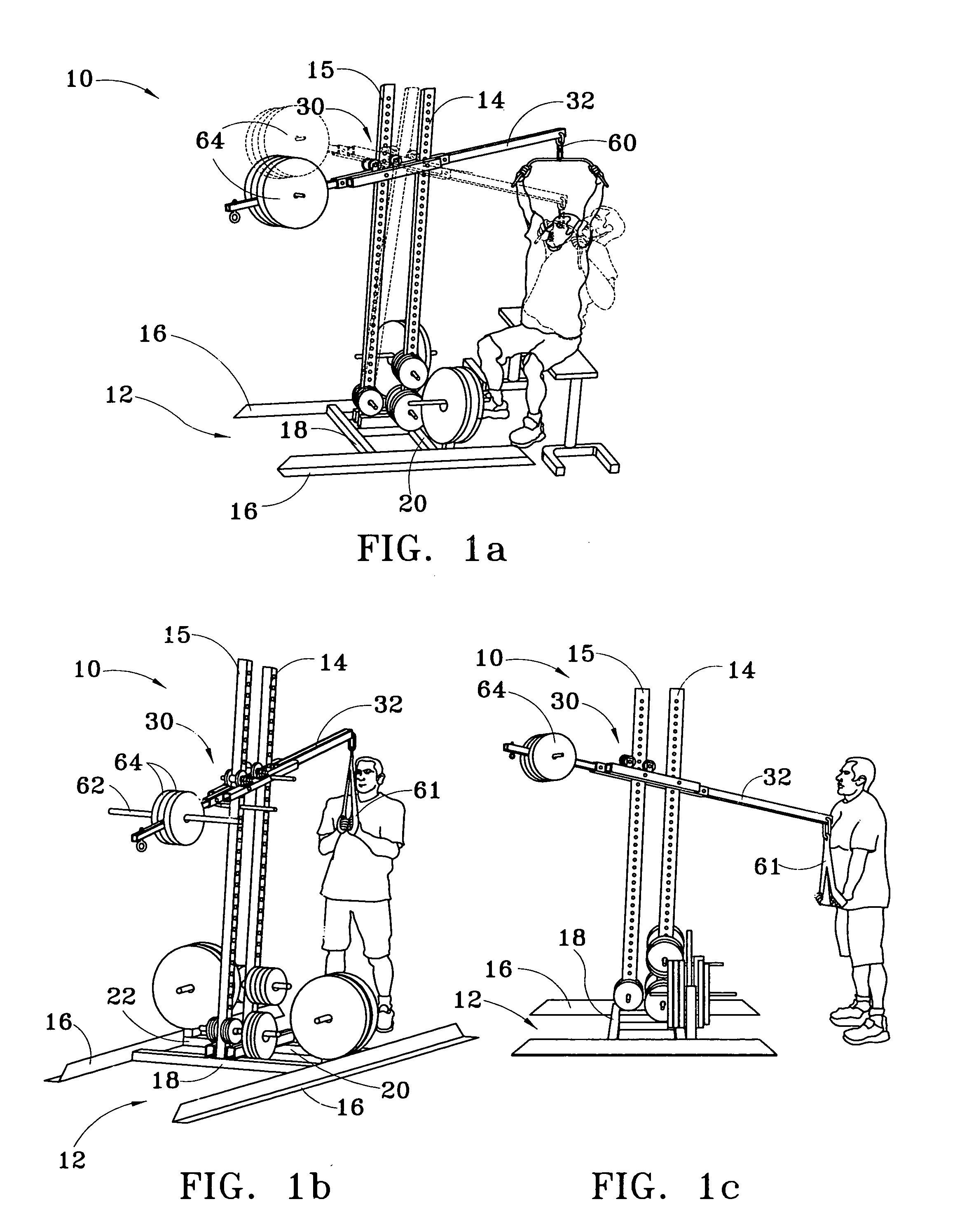
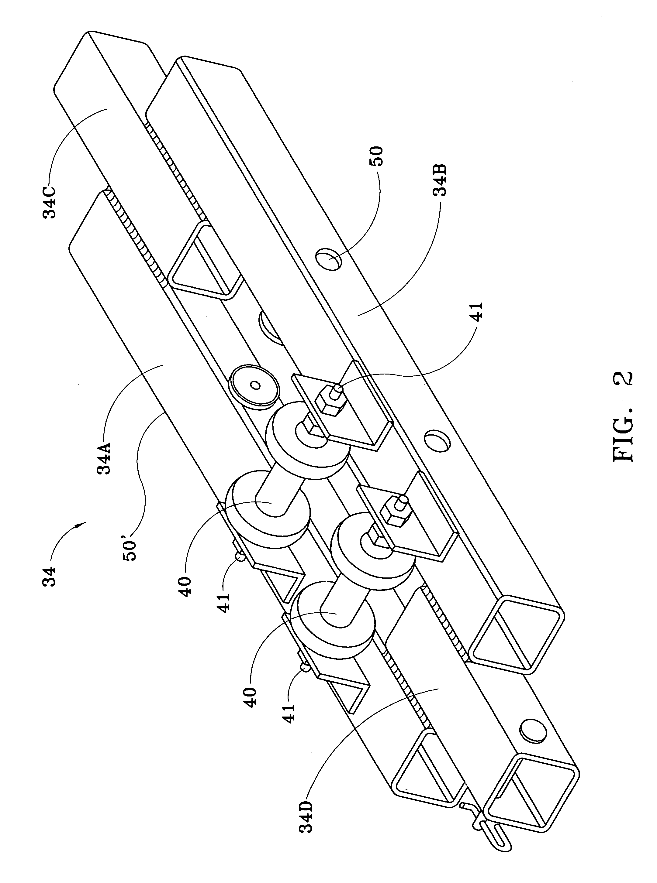
[0049]Referring now to FIGS. 1–6, my weight exercise device, denoted generally by the numeral 10. For illustrative purposes only, the device is shown in FIGS. 1(a), 1(b), 1(c) and 1(d) in use by a trainee engaged in pulldowns (FIGS. 1(a) and 1(b)) and triceps extension (FIGS. 1(c) and 1(d), but the device is very versatile and can be used in an additional thirty-eight other kinds of weight lifting exercises. The device 10 comprises a base 12, a front, upstanding stanchion 14 that has a first, lower end rigidly attached to the base 12 and an opposite free end; a rear, pivoting stanchion 15 spaced rearward from and coplanar with the front stanchion 14, and has a lower end pivotally attached to the base; and a longitudinally-elongated lever arm assembly 30. As may best be seen in FIG. 6, the base 12 includes a pair of longitudinally-directed, laterally spaced-apart angle irons 16 joined by a parallel pair of laterally directed, spaced-apart, cross beams 18, 20 of equal length. A pair o...

second embodiment

[0057]Body engaging means for the device 10′ are illustrated in FIG. 14B, and include a lift arm 74′, a front beam 32′ that carries an I bolt and that can also be used as a rear beam, and a padded pair of shoulder bars 111. To facilitate attachment of body-engaging means to the device 10′, the rear and front members 84, 86 of the lever arm assembly 80 each have a rectangular opening. The lift arm 74′ has a shank portion 74S′ fashioned from square tubing and adapted for attachment to the front member 86 or rear member 84. Similarly, the padded pair of shoulder bars 111 has a shank portion 111S fashioned from square tubing and adapted for attachment to the front member 86 and to the rear member 84. Weight engaging means may be suspended from the front beam 32′ by a quick release clip 162 that attaches to the I bolt 99.

[0058]To use the second embodiment of the device 10′, the trainee attaches a front beam 32′ to the front end of the lever arm assembly 80 or a rear beam 36 to the rear e...


PUM


Abstract

A weight training device for providing substantially uniform resistance throughout the range of motion of each of a variety of weight lifting exercises. Upstanding front and rear stanchions are attached to front and rear portions of a base, respectively. In a first embodiment, the front stanchion is rigidly attached to the base, the rear stanchion is pivotally attached to the base, and a lever arm assembly is pivotally attached to the front stanchion and includes a dolly cage attached to the rear stanchion that forces the rear stanchion to pivot toward and away from the front stanchion as the assembly is pivoted in a vertical plane by a weight trainee against the resistance of weight suspended from the assembly. In a second embodiment, the front stanchion is mounted for reciprocal, vertical motion on a rod attached to the base. A plurality of weight plates are disposed below the front stanchion in vertical, stacked relation, any or all of which can be suspended from the front stanchion by insertion of a stack pin through any one of the plates and into an aperture in a stack pin rod suspended from the front stanchion. A lever arm assembly has a front portion pivotally attached to the front stanchion and a rear portion pivotally attached to the rear, pivoting stanchion, such that when a trainee pivots the assembly in a vertical plane against the resistance of the weights, the rear stanchion pivots toward the front stanchion.

Description

CROSS REFERENCE TO RELATED APPLICATIONS[0001]This application is related to U.S. provisional patent application No. 60 / 534,779 by the same applicant with filing date Jan. 5, 2004.STATEMENT REGARDING FEDERALLY APPROVED RESEARCH OR DEVELOPMENT[0002]None.BACKGROUND OF THE INVENTION[0003]1. Field of the Invention[0004]This invention relates to body exercising apparatus and more particularly to weight exercise machines that provide a substantially uniform resistance throughout the range of motion of each of several different kinds of weight lifting exercises.[0005]2. Background Art[0006]Weight lifting exercises have long proven effective for muscle and general body building. For a weight trainee who is a trained athlete or who has otherwise acquired adequate strength and muscle conditioning, bar bells and dumbbells can be used in performing bench presses, leg squats, biceps curls, triceps extensions and other weight training exercises. Bar bells and dumbbells, however, can inadvertently ...

Claims


Application Information

Patent Timeline
Patent Type & Authority Patents(United States)
IPC IPC(8): A63B21/00A63B21/06A63B21/062B65F9/00B65G67/00
CPCA63B21/0615A63B21/08A63B21/1492A63B23/03508A63B23/03525A63B21/1469A63B21/062A63B2021/0616A63B21/0628A63B21/4035A63B21/0616A63B21/4047
Inventor CARLE, JOHN T.
Owner CARLE JOHN T
Learn More