Calibration method and device in electronic component mounting apparatus

a technology of electronic components and mounting devices, which is applied in the direction of electronic components, television systems, printed circuit manufacture, etc., can solve the problems of increasing equipment costs, increasing component mounting costs, and inability to build an electronic component mounting line capable of always attaining maximum productivity

Active Publication Date: 2006-09-05
FUJI CORP
View PDF8 Cites 17 Cited by
  • Summary
  • Abstract
  • Description
  • Claims
  • Application Information

AI Technical Summary

Benefits of technology

[0013]It is therefore a primary object of the present invention to provide an improved calibration method and device capable of easily and precisely calibrating the distance between the center line of a component pick-up portion of a component placing device and the optical axis of a board recognizing camera after installation of the component placing device in an electronic component mounting device of the type wherein plural component placing devices different in kinds or performance can be used replaceably.
[0016]In the calibration method and device according to the present invention, since the reference mark is provided on the base frame thereby to be held stably, the respective positional relations of the optical axes of the both cameras relative to the reference mark can be detected reliably in a stable state. And, when the movable table is stopped at the predetermined position with respect to the coordinate origin, the position of the optical axis of the component recognizing camera relative to the coordinate origin can be calibrated precisely based on the position of the optical axis of the board recognizing camera relative to the coordinate origin.

Problems solved by technology

Therefore, in the former method of constructing an electronic component mounting line in a combination of high-speed, small-component mounting apparatuses and different-shape-component mounting apparatuses, the mounting operation of electronic components must be carried out with either one of the electronic component mounting apparatus being lowered in operation efficiency, whereby a problem arises in that it is impossible to build an electronic component mounting line capable of always attaining the maximum productivity.
This causes a problem that the cost for the equipment rises to be reflected on an increase in the component mounting cost.
Further, new types of components to be mounted on circuit boards are developed day by day, thereby making it impossible to predict the new types at the time of designing the electronic component mounting apparatus.
Therefore, in designing electronic component mounting apparatuses, it has to be taken into consideration to deal with more types of components than those present at the time of such designing, which disadvantageously results in redundant or excess equipments thereby increasing the cost for equipments.
However, there remains a problem that the measuring method involves errors in the shape of the component as well as in the holding position on the suction nozzle.
This may disadvantageously cause the suction nozzle to be deformed due to the gravity of the measuring jig, thereby resulting in measurement errors, or causes the measuring jig to be detached from the suction nozzle with a small external force.
Therefore, problems arise in that it is not easy to practice to measure the setting position of the board recognizing camera relative to the suction nozzle with the measuring jig being held not to be detached from the suction nozzle.

Method used


Image

  • Calibration method and device in electronic component mounting apparatus
  • Calibration method and device in electronic component mounting apparatus
  • Calibration method and device in electronic component mounting apparatus

Examples


first embodiment

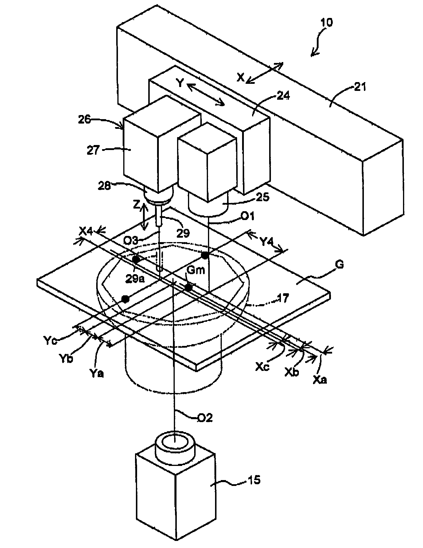
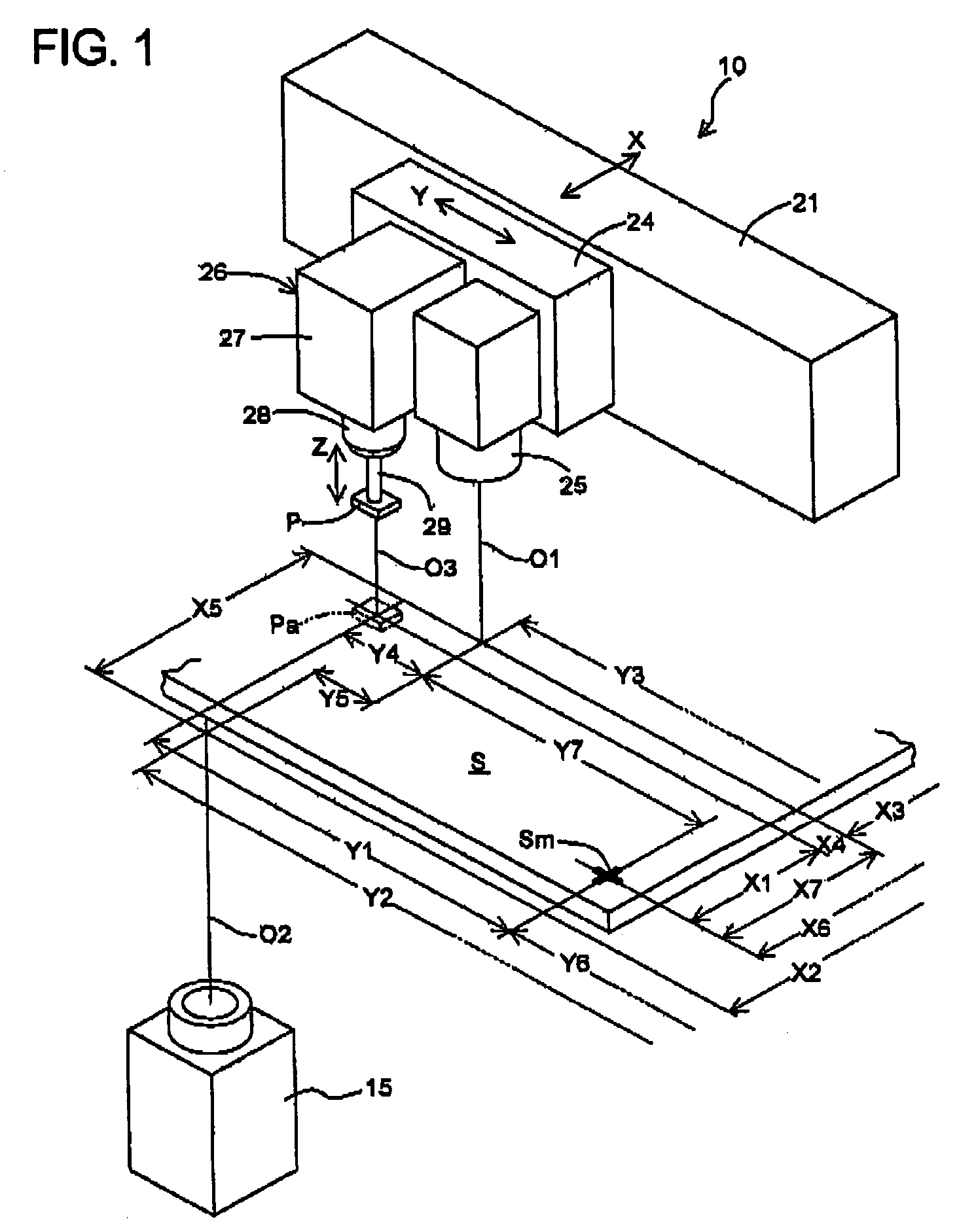
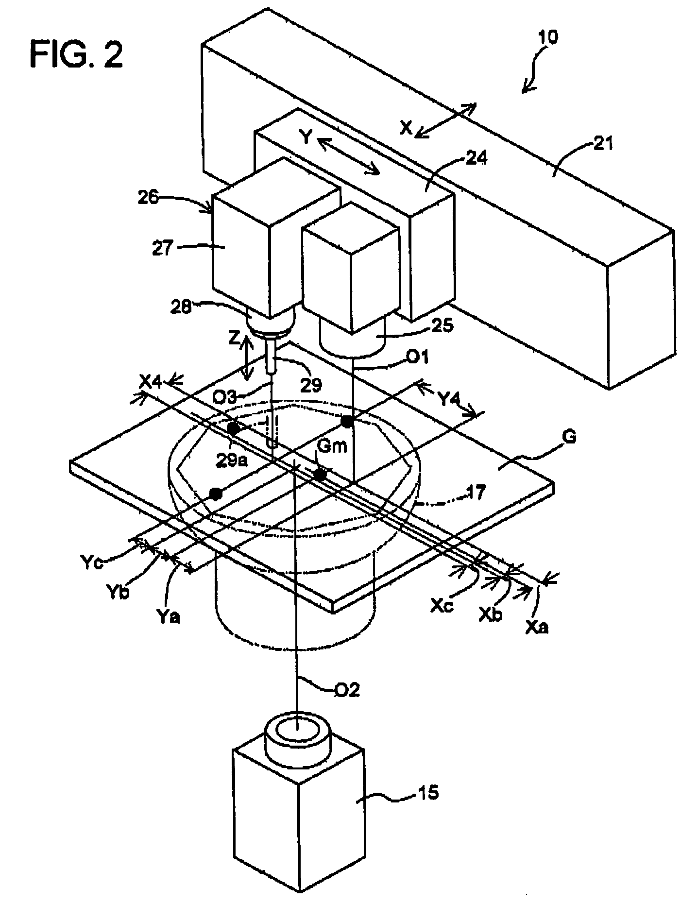
[0037]Next, the operation in the first embodiment for performing these calibrations will be described with reference mainly to FIGS. 1 to 3. Prior to this operation, as shown in FIGS. 2 and 3, a reference gauge G which is provided with one or several reference marks Gm of each such a shape as spot, cross, or the like on a colorless, transparent glass plate is set on a cover glass 18 of the upper end member 17 with the reference mark or marks Gm residing in the visual field of the component recognizing camera 15. Then, the movable table 24 is moved to and stopped at such a predetermined position that the reference mark Gm comes in the visual field of the board recognizing camera 25 and that at the same time, the end of the suction nozzle 29 of the component placing device 26 remains or resides in the visual field of the component recognizing camera 15. The positional relation (distance X3 and distance Y3 in FIG. 3) of the circuit board camera optical axis O1 with respect to the coord...

second embodiment

[0049](Second Embodiment)

[0050]In the modification as described above, the measurements of the distances Xa, Ya, Xb, Yb, Xc, and Yc are laborious, because they must be done twice with the movable table 24 positioned at the first position and the second position. In the second embodiment shown in FIG. 4, however, even in the case that the suction nozzle center line O3 and the circuit board camera optical axis O1 are set further apart from each other, the calibration for the positional relation between the circuit board camera optical axis O1 and the component camera optical axis O2 and the calibration for the positional relation between the circuit board camera optical axis O1 and the suction nozzle center line O3 can be done with the movable table 24 being maintained stopped at a single predetermined position as is the case of the foregoing first embodiment.

[0051]The second embodiment is different from the first embodiment in that a reference gauge Ga provided with first and second ...

third embodiment

[0058](Third Embodiment)

[0059]Next, description will be made as to the third embodiment in which a component placing device 40 with a rotary head 42 is detachably or replaceably installed on the movable table 24. As shown in FIG. 7, the component placing device 40 is provided with a head frame 41 which is installed on the movable table 24. Carried on the lower part of the head frame 41 for rotary movement about a vertical axis is a cylindrical rotary head 42, which holds a plurality (e.g., eight) of spindles 44n to be movable reciprocatively in the vertical direction (Z direction). Each spindle 44n is urged upward by a compression spring (not shown) and has a suction nozzle 29n attached at its lower end in coaxial alignment therewith.

[0060]The rotary head 42 is intermittently rotated by a servo motor 43 mounted on the head frame 41 thereby to position the suction nozzles 29n at respective predetermined positions. Each spindle 44n which has been stopped at a mounting point (mounting ...


PUM

PropertyMeasurementUnit
optical axisaaaaaaaaaa
opticalaaaaaaaaaa
flexibilityaaaaaaaaaa

Abstract

In an electronic component mounting apparatus capable of replacing a component placing device with any of plural other component placing devices different in performance, the distance between the center line of a component pick-up portion of a replaced component placing device and the optical axis of a board recognizing camera is calibrated easily and precisely. A movable table is positioned so that a reference mark provided on a base frame to reside in the visual field of a component recognizing camera comes in the visual field of a board recognizing camera and that at the same time, the end of the component pick-up portion of the replaced component placing device comes in the visual filed of the component recognizing camera. The board recognizing camera is used to detect the positional relation of the optical axis thereof relative to the reference mark, while the component recognizing camera is used to detect the positional relations of the optical axis thereof relative to the reference mark and relative to the center line of the component pick-up portion. These detected positional relations are used to calculate the positional relation between the optical axis of the board recognizing camera and the center line of the component pick-up portion.

Description

INCORPORATION BY REFERENCE[0001]This application is based on and claims priority under 35 U.S.C. sctn. 119 with respect to Japanese Applications No. 2002-329994 filed on Nov. 13, 2002 and No. 2003-368435 filed on Oct. 29, 2003, the entire contents of which are incorporated herein by reference.BACKGROUND OF THE INVENTION[0002]1. Field of the Invention[0003]The present invention relates to a calibration method and device in an electronic component mounting apparatus for mounting electronic components on substrates or circuit boards. In particular, it relates to a calibration method and device for preventing errors in the mounting position of components when a component placing device replaces another which is different in performance.[0004]2. Discussion of the Related Art[0005]Electronic components that are mounted on circuit boards by electronic component mounting apparatuses of this type include small-type electronic components which are used in a large quantity such as chips and la...

Claims


Application Information

Patent Timeline
Patent Type & Authority Patents(United States)
IPC IPC(8): G01V8/00H05K3/30H05K13/04H05K13/08
CPCH05K13/0413H05K13/0452Y10T29/49131H05K13/0812H05K13/0815
Inventor KODAMA, SEIGOSUHARA, SHINSUKENOZAWA, MIZUHO
Owner FUJI CORP
Why Eureka
Try Eureka