Liquid crystal display assembly for reducing optical defects

a liquid crystal display and assembly technology, applied in non-linear optics, instruments, optics, etc., can solve problems such as optical shadows, operational failures, and improper operation of pixel arrays, and achieve the effects of minimizing the amount of forces and stresses, reducing the amount of transmission of stresses, and improving heat dissipation

Inactive Publication Date: 2006-09-05
NAT SEMICON CORP
View PDF6 Cites 10 Cited by
  • Summary
  • Abstract
  • Description
  • Claims
  • Application Information

AI Technical Summary

Benefits of technology

[0018]The described arrangements have numerous advantages and permit an LCD assembly which minimizes the amount of forces and stresses that lead to optical defects. The stabilizers, in addition to supporting the cell, also act to contain an encapsulating material used to protect the bonding wires. The support material, in addition to minimizing transmission of stresses, also allows improved heat dissipation from the LCD cell.
[0019]In another embodiment, a method for constructing the LCD assembly is described. As a result of the reduced temperature sensitive curing involved in the present invention, cycle time, or the time required to construct the LCD assembly, is reduced to less than five hours.

Problems solved by technology

Variances in these distances may often times cause the pixel array to function improperly or cause operational failure.
One problem with conventional rigid display device constructions where the substrate 27, the glass plate 24 and the silicon die 21 are all attached are optical defects due to warping.
At a minimum, these internal stresses cause optical defects such as variations in color uniformity and fringes, and variations in the cell gap thickness which may cause optical shadows.
As these optical defects may be produced by deformations as small as 0.25 microns, minor stresses may substantially reduce optical quality.
Upon more extensive high temperature thermal cycling during operation, additional occurrence of optical fringes and optical non-uniformity may even further compromise the performance of the LCD assembly.
As viewed in the cross-sectional view of FIG. 5, central thinning of the cell is caused which results in defects such as discoloration and the appearance of optical shadows.
Another cause of optical defects due to stress occurs during construction of the small scale LCD assembly 20.

Method used


Image

  • Liquid crystal display assembly for reducing optical defects
  • Liquid crystal display assembly for reducing optical defects
  • Liquid crystal display assembly for reducing optical defects

Examples


Embodiment Construction

[0037]In the following detailed description of the present invention, numerous specific embodiments are set forth in order to provide a thorough understanding of the invention. However, as will be apparent to those skilled in the art, the present invention may be practiced without these specific details or by using alternate elements or processes. In other instances well known processes, procedures, components, and circuits have not been described in detail so as not to unnecessarily obscure aspects of the present invention.

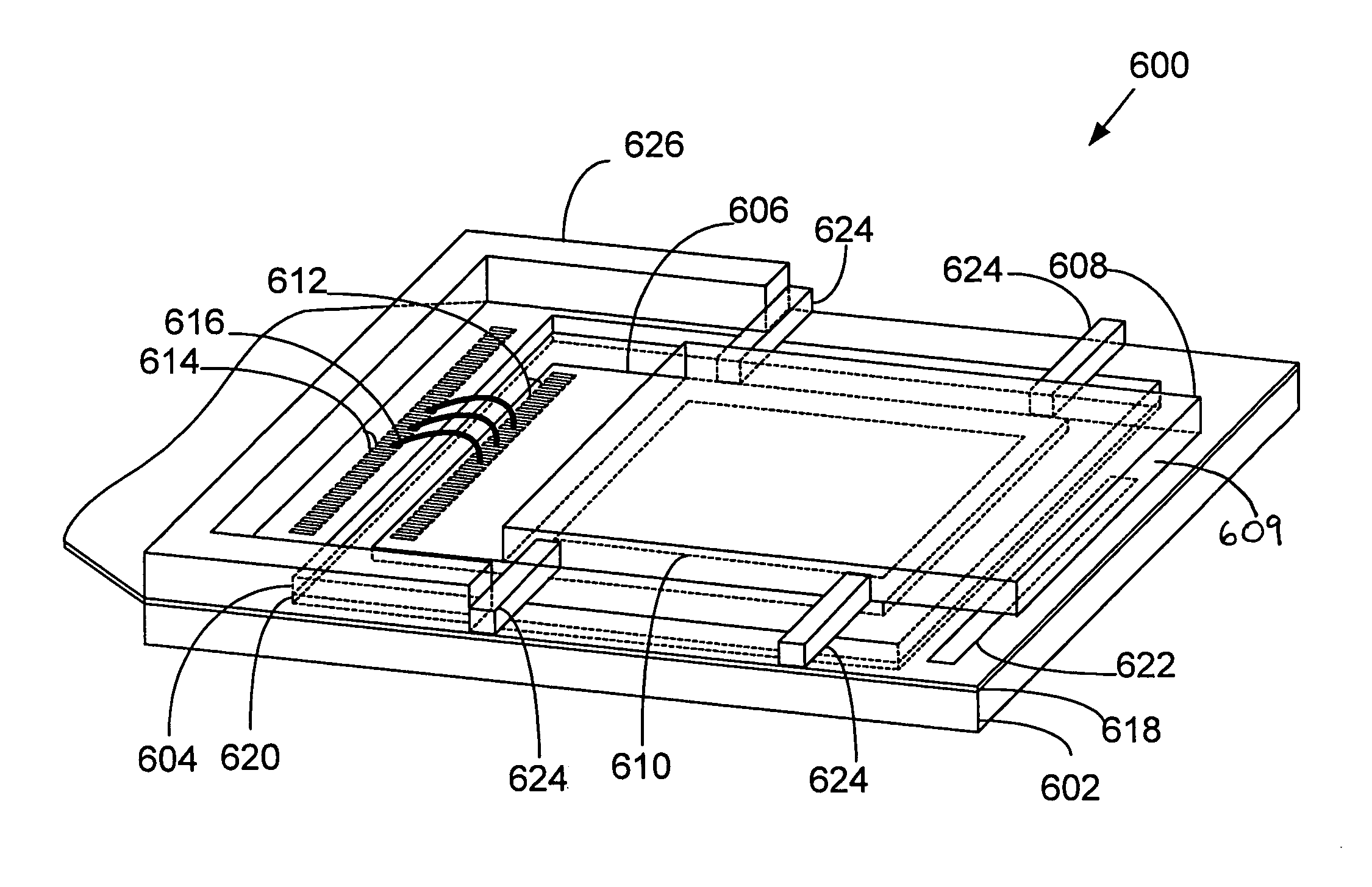
[0038]Referring initially to FIGS. 6–9, a small scale liquid crystal display (LCD) assembly 600 according to one embodiment of the present invention will be described. The liquid crystal display 600 includes a substrate 602 having a recess 604 that acts as a containment chamber for receiving a die 606 attached to a transparent plate 608. A liquid crystal material is disposed between the die 606 and the transparent plate 608. Generally, the die 606, the transparen...


PUM

PropertyMeasurementUnit
thicknessaaaaaaaaaa
thicknessaaaaaaaaaa
cycle timeaaaaaaaaaa

Abstract

An improved packaged liquid crystal display (LCD) assembly is described. A recess is used to house a support material while the LCD cell 609 is positioned at least partially within the containment structure. A plurality of spaced apart stabilizers are attached from the sides of the LCD cell 609 to the substrate without transmitting residual stresses induced during fabrication and operation. A support material is dispensed in the recess such that it provides support for the LCD cell 609 without transmitting residual stresses from the substrate. The described arrangements permit an LCD assembly which minimizes the amount of forces and stresses that lead to optical defects. The stabilizers, in addition to supporting the cell, also act to contain the encapsulating material used to protect the bonding wires. The support material, in addition to minimizing transmission of stresses, also provides improved heat dissipation from the LCD cell 609. In another embodiment, a method for constructing the LCD assembly is described.

Description

RELATED APPLICATIONS[0001]This application is related to application Ser. No. 09 / 130,631 filed Aug. 8, 1998, which is incorporated herein by reference.FIELD OF THE INVENTION[0002]The present invention relates, generally to liquid crystal display assemblies and, more particularly, relates to miniature liquid crystal display assemblies constructed to reduce optical defects.BACKGROUND OF THE INVENTION[0003]In the recent past, substantial research and development resources have been directed toward small scale Liquid Crystal Display (LCD) and light valve technologies. These miniature LCD assemblies are typically employed in high resolution projection displays, such as a reflective LCD projectors, SXGA formats (1,280×1,024 pixel resolution) and even HDTV formats (above 1,000 line resolution), or the like.[0004]Briefly, as shown in FIGS. 1 and 2, a conventional small scale LCD assembly 20 is illustrated including a die 21 having a pixel array 22. This pixel array 22 is typically composed ...

Claims


Application Information

Patent Timeline
Patent Type & Authority Patents(United States)
IPC IPC(8): G02F1/1333G02F1/1345
CPCG02F1/133308G02F1/13452G02F1/133385
Inventor MATHEW, RANJAN J.TAKIAR, HEMMURRAY, CADEFRIDLYAND, TONYA
Owner NAT SEMICON CORP
Why Eureka
Try Eureka