Radio-wave clock

a radio wave and clockwork technology, applied in the field of radio wave watches, can solve the problems of unavoidable increase in cost, unavoidable increase in lead time, and inability to work on the surface in a formatively complicated way to enhance the appearance, so as to reduce the reception sensitivity of radio waves through the opening of the dial. , the effect of excellent appearan

Active Publication Date: 2006-09-05
SEIKO INSTR INC
View PDF5 Cites 5 Cited by
  • Summary
  • Abstract
  • Description
  • Claims
  • Application Information

AI Technical Summary

Benefits of technology

[0011]The radio-wave watch of the invention has its dial made of a metal so that it is easily realized with an excellent appearance at a low cost. Moreover, the radio-wave watch of the invention has its receiving antenna housed in the case so that its contour can be prevented from becoming large. Especially, the radio-wave watch of the invention has its dial formed to have the opening so that the radio waves can go into the case through the opening of the dial even when the dial is made of a metal. In the radio-wave watch of the invention, moreover, the receiving antenna is arranged on the back of the opening of the dial and at the position to confront the opening substantially. Therefore, the radio waves having entered the inside of the case through the opening can be reliably received by the receiving antenna so that the drop of the receiving sensitivity of the standard radio waves can be minimized although the dial is made of a metal.
[0017]In this radio-wave watch, “the time lapse indicating means arranged in the case between the dial and the receiving antenna indicates the lapse of time within the range of the opening”, so that the opening of the dial can be used to indicate the lapse of time while retaining the excellent appearance owing to the metallic dial. In the radio-wave watch of the invention, moreover, “the time lapse indicating means arranged in the case between the dial and the receiving antenna is substantially made of a non-metal” so that the possibility of lowering the reception sensitivity of the radio waves through the opening of the dial can be minimized by the time lapse indicating means.

Problems solved by technology

In case, however, the dial made of a resin is used, as proposed in JP-A-2002-107463, a formatively complicated working on the surface is required for enhancing the appearance.
This requirement makes it unavoidable to raise the cost and to elongate the fabrication process and accordingly the leadtime.

Method used


Image

  • Radio-wave clock
  • Radio-wave clock
  • Radio-wave clock

Examples


Embodiment Construction

[0030]The present invention will be described in connection with preferred modes of embodiment with reference to the accompanying drawings.

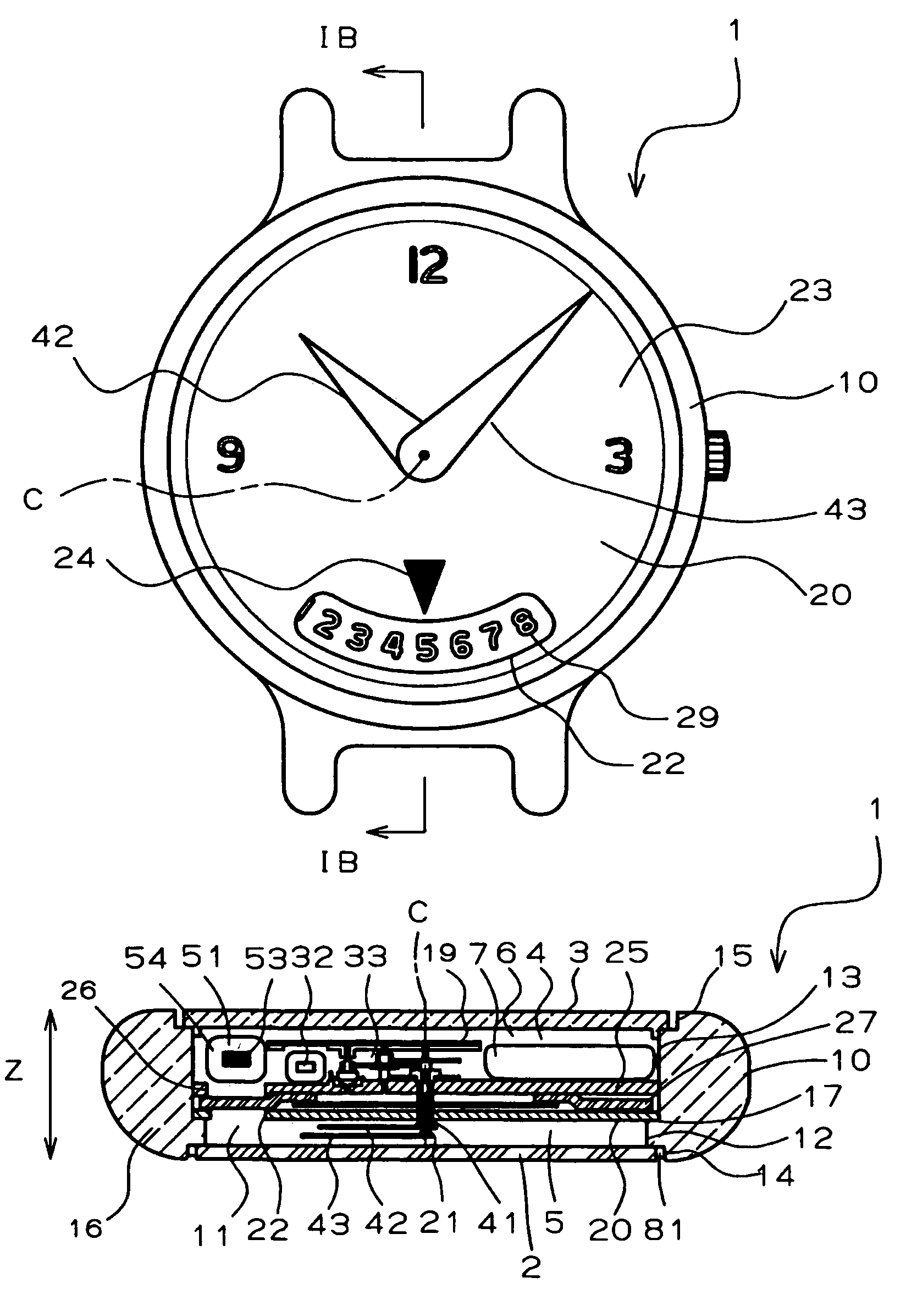
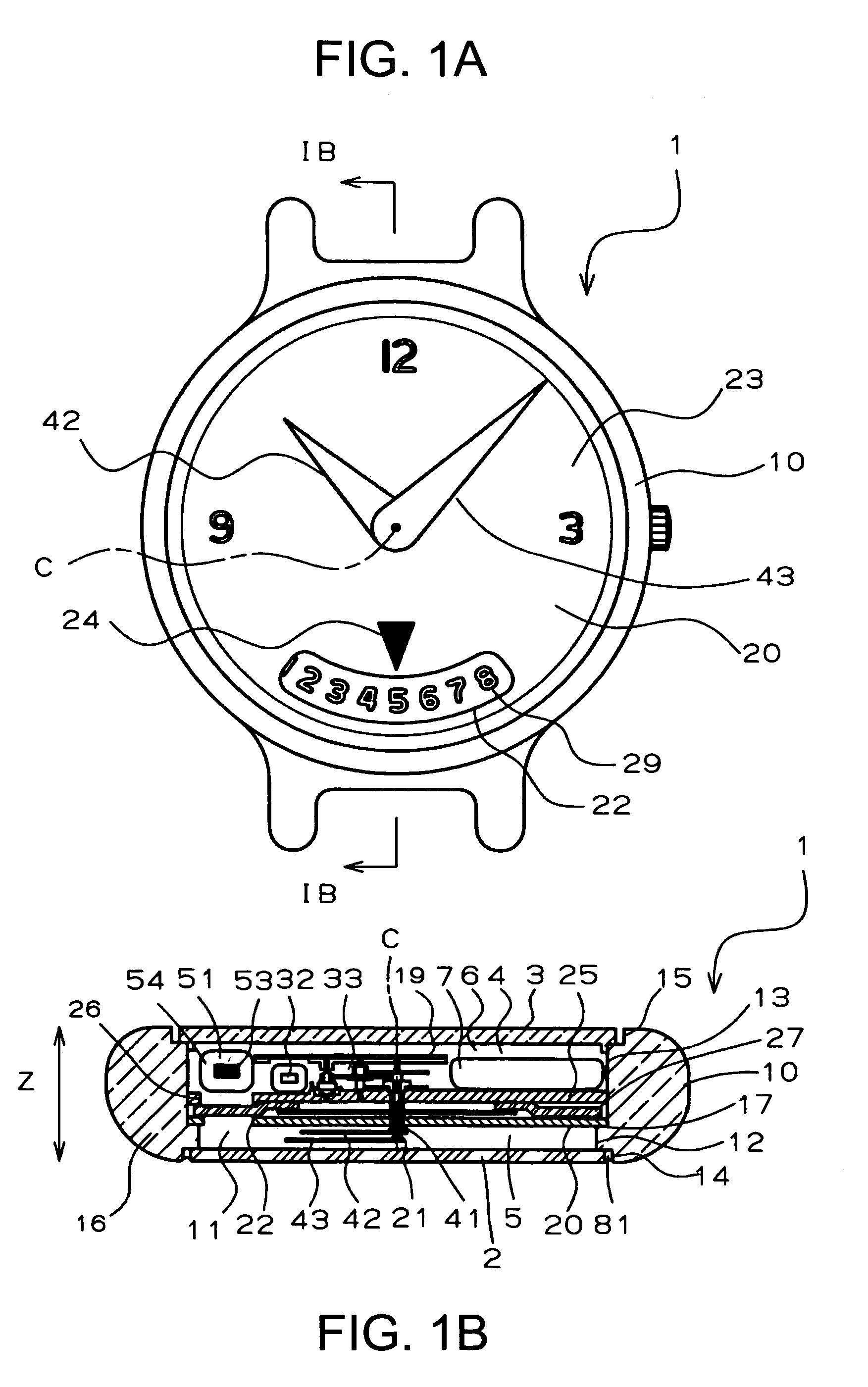
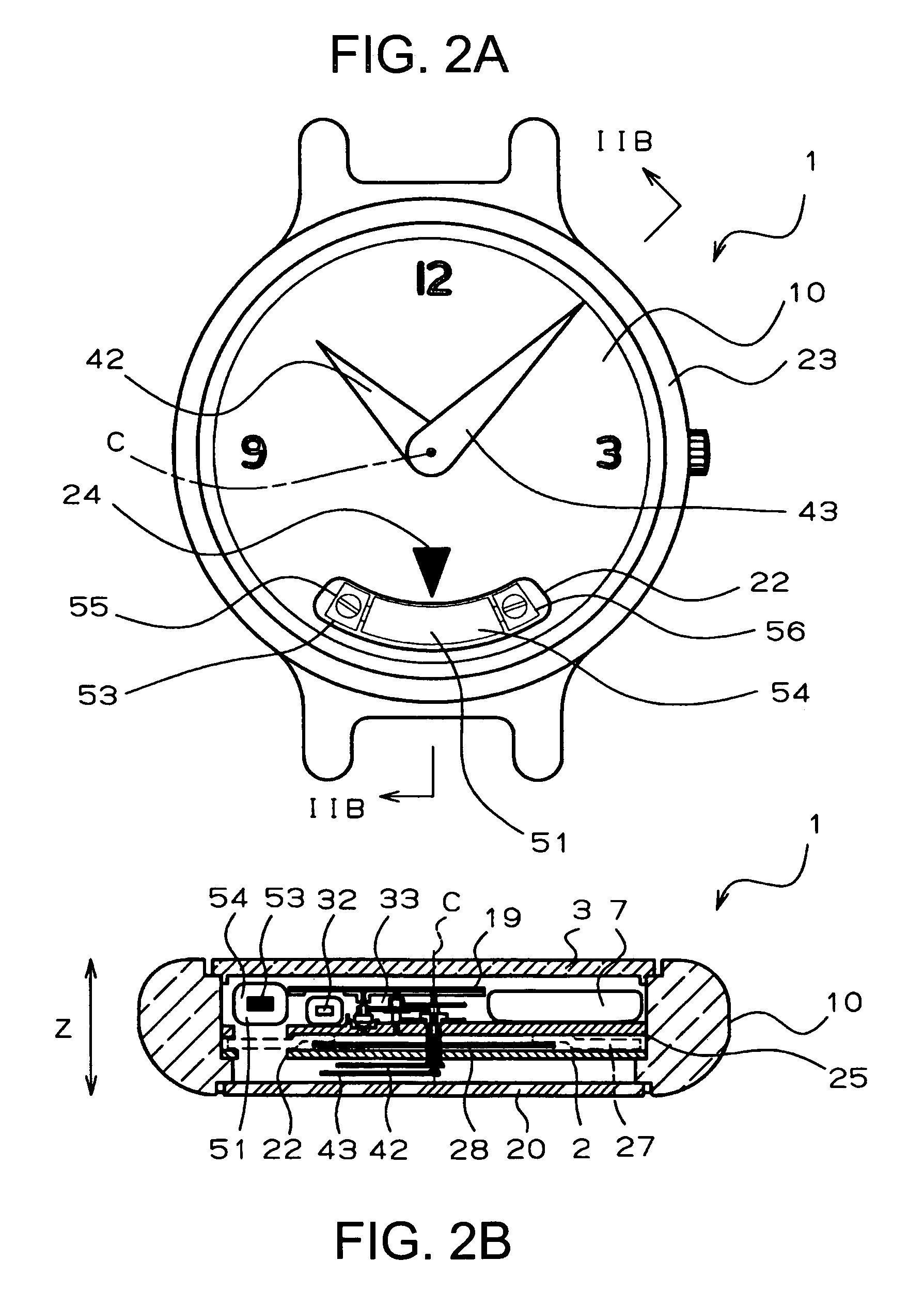
[0031]FIG. 1 to FIG. 3 show a radio-wave watch 1 of a first preferred embodiment according to the invention. The radio-wave watch 1 is provided, in the mode of a wrist watch, with a generally annular case 10, which has an opening 11 composed of a diametrically-small hole portion 12 on the front side and a diametrically-large hole portion 13 on the backside. A glass 2 is fitted through a packing 81 in a diametrically-large annular groove portion 14 on the open end of the diametrically-small hole portion 12, and a case back 3 is screwed in the open end 15 of the diametrically-large hole portion 13. As a result, a chamber 4 is formed in the case 10 by the circumferential wall 16 of the case 10, the glass 2 and the case back 3.

[0032]A dial 20 made of a metallic disc is placed on a step portion 17 between the diametrically-small hole portion 12 and th...


PUM


Abstract

To provide a radio-wave watch, which can have an excellent appearance and can minimize the drop of the sensitivity of receiving radio waves, while suppressing the size enlargement and the cost for the contour. A radio-wave watch comprises a metallic dial having an opening, and a receiving antenna for receiving the standard radio waves containing the time data. The receiving antenna is arranged on the back of the opening of the dial and in a case at a position to confront the opening. The receiving antenna is arranged in the case at a spacing from the dial. Time lapse indicating means substantially formed of a non-metal is arranged in the case between the dial and the receiving antenna for indicating the time lapse within the range of the opening.

Description

BACKGROUND OF THE INVENTION[0001]1. Field of the Invention[0002]The present invention relates to a radio-wave watch and, more particularly, to a radio-wave watch suited for taking the mode of a wrist watch.[0003]2. Description of the Prior Art[0004]An antenna for receiving the standard radio waves is indispensable for the radio-wave watch, which adjusts its indication time to time data by receiving the standard radio waves containing the time data.[0005]With a view to receiving the standard radio waves in high sensitivity by that antenna, it has been proposed (in JP-A-8-307141) to arrange a loop-shaped antenna in the outer circumference of the watch case.[0006]In the radio-wave watch proposed in JP-A-8-307141, however, the contour or size may become so large as to provide a contour, exceeding a desired extent as the radio-wave watch to be worn oh the wrist.[0007]On the other hand, it has also been proposed (in JP-A-2002-107463) to house the antenna in the case. In JP-A-2002-107463, ...

Claims


Application Information

Patent Timeline
Patent Type & Authority Patents(United States)
IPC IPC(8): G04C11/02G04B37/00G04R20/00G04R20/08G04R60/10
CPCG04R60/12G04G21/04
Inventor MATOGE, AKIHIROMAEHARA, YOSHIFUMI
Owner SEIKO INSTR INC
Why Eureka
Try Eureka