Printing apparatus with first and second measuring means for obtaining a conveying amount of a printing medium

a technology of conveying amount and printing medium, which is applied in the direction of spacing mechanism, thin material processing, printing, etc., can solve the problems of high cost, unstable speed control, and difficulty in speed control carried out in accordance with this pulse signal, so as to eliminate the conveyance error of the conveyor roller and high speed

Active Publication Date: 2006-09-12
CANON KK
View PDF11 Cites 46 Cited by
  • Summary
  • Abstract
  • Description
  • Claims
  • Application Information

AI Technical Summary

Benefits of technology

[0020]The present invention has been made to solve the above-mentioned various problems, and an object thereof is to eliminate the conveyance error of the conveyor roller as much as possible and realize the high-accuracy and high-speed conveyance of the printing medium.

Problems solved by technology

Recently, however, the requirement has been more complicated, for example, when a high grade image having a photographic image quality is printed by using ink droplets of a micro-size ejected at a higher density and a higher accuracy.
For example, if the conveying speed is extremely decelerated, there is a problem in that an output from the rotational angle sensor 1006 becomes discrete to make the speed control to be very difficult.
Accordingly, the speed control carried out in accordance with this pulse signal is liable to be unstable.
However, this is limitative in practice in the manufacture of the code wheel.
This method, however, is problematic because a size of the printing apparatus itself becomes larger.
Also, the eccentricity during the attachment of the code wheel 1005 and the conveyor roller 1001 is problematic, and not negligible when the control is more precisely carried out.
In addition, there is another problem in the accuracy of the stop position.
In such a case, there is a risk in that the stop position may fluctuate relative to the presumed position due to the variation of the mechanical frictional load or others.
Drawbacks will be described below, which may occur when the prior art method having the above-mentioned problems is used for controlling the printing medium under the recent circumstances.
Thus, the actual conveying distance is variable relative to the same rotational angle of the conveyor roller in accordance with kinds of the conveyed object, whereby there is a problem in that the accurate conveying distance is not obtainable by solely controlling the rotational angle of the conveyor roller.
Thereby, the actual conveying distance more or less contains an error of the above-mentioned mechanical system even if the rotational angle is correctly controlled by using the sensor.
This error is not negligible in the high conveying accuracy required for the recent printing apparatus.
In this case, however, since a size of the wheel is directly related to a size of the printing apparatus, the enlargement of the wheel size must be naturally limited under the recent circumstances in which the minimization of an apparatus size is important.
Accordingly, there is also a limitation in the improvement in the resolution of the rotational angle; i.e., the conveyance accuracy.
A slight error in the conveyance performance inevitably exists between the first and second conveyor rollers due to the difference in the mechanical transmission passage.
This problematic in that such an error results in the shift of the printing position in the printing of the rear end portion and causes a significant drawback of the image.
However, such a countermeasure causes a novel problem in that the printing speed becomes lower.

Method used


Image

  • Printing apparatus with first and second measuring means for obtaining a conveying amount of a printing medium
  • Printing apparatus with first and second measuring means for obtaining a conveying amount of a printing medium
  • Printing apparatus with first and second measuring means for obtaining a conveying amount of a printing medium

Examples


example 1

[0065]FIG. 9 is a flow chart for illustrating the processing of CPU 101 for controlling the conveyance of the printing medium. FIGS. 10A to 10E are illustrations of the conveyance of the printing medium at the respective timing.

[0066]With reference to these drawings, upon starting the printing, the supply of the printing medium 1007 is initiated at step 1. The printing medium 1007 is conveyed in the direction indicated by an arrow in FIG. 10A.

[0067]At step 2, it is determined whether or not a front end of the printing medium 1007 is detected by the paper-end sensor 33. The supply of the printing medium at step 1 continues until the front end detected at step 2.

[0068]When the front end of the printing medium 1007 is detected at step 2, the routine proceeds to step 3 at which the control of a conveying speed and a position is commenced by the rotational angle sensor 1006. This stage corresponds to FIG. 10B.

[0069]At step 4, it is determined whether or not the existence of the printing ...

example 2

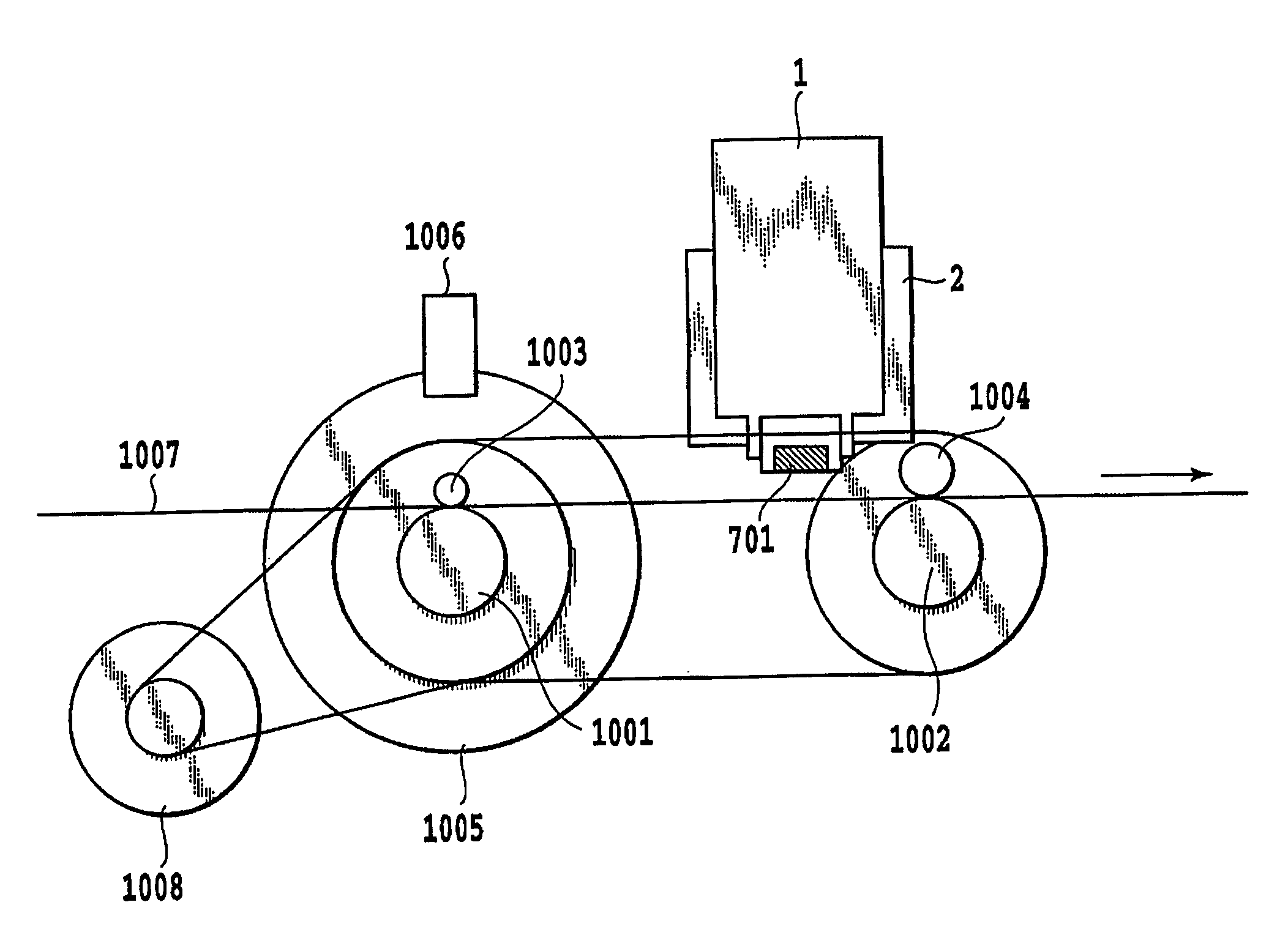
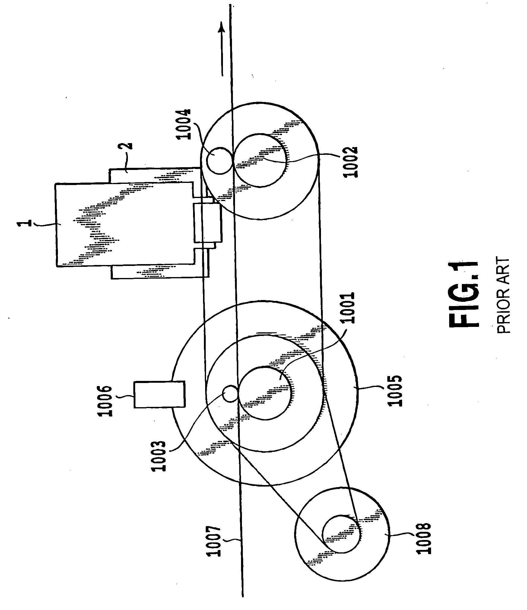
[0075]In this example, while the conveying distance of the printing medium is corrected in accordance with kinds thereof as described in Example 1, a position of the conveyed printing medium is determined and the printing medium is made to stop at higher accuracy than the resolution of the rotational angle sensor 1006.

[0076]The resolution of the moving distance reading sensor 701 used in this example is higher than the resolution of the rotational angle sensor 1006. Accordingly, it is possible to set the conveyance resolution and then the printing resolution at a higher level while maintaining the printing apparatus in a small size without enlarging a diameter of the code wheel 1005 used for the rotational angle sensor 1006.

[0077]The actual operation will be described when the conveying distance is larger than a predetermined value, the conveyance control is carried out by the rotational angle sensor 1006 until the conveying distance reaches a value which is closer to the target val...

example 3

[0079]In this example, a control method carried out at a low conveying speed will be described, which is difficult to be controlled by the rotational angle sensor 1006 having a lower resolution, while correcting the conveying distance of the printing medium in accordance with kinds thereof as described in Example 1.

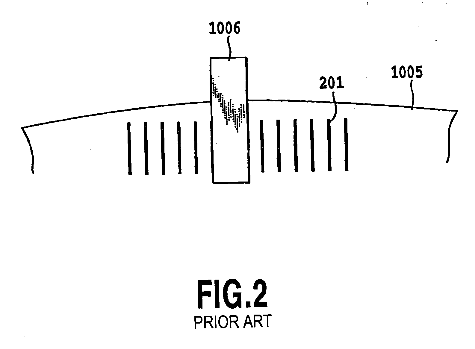
[0080]In the rotational angle sensor 1006 outputting a pulse at a timing when the conveyor roller 1001 rotates at predetermined pitches, when the conveying speed; i.e., the roller rotational speed varies, an interval between the adjacent pulses becomes discrete. Even in such a state, it is possible to relatively favorably carry out the algorithm for controlling the speed, if the rotational speed is maintained at a certain level. However, since the rotational speed is considerably lowered immediately before the roller stops at a predetermined position, the control becomes very unstable.

[0081]This phenomenon will be described in more detail below. Immediately before the pri...


PUM


Abstract

A printing medium is conveyed at a high speed and high accuracy by reducing the conveyance error of a conveyor roller as much as possible. For this purpose, the printing apparatus includes first measuring unit for obtaining a conveying amount of said printing medium by measuring a rotational amount of the conveyor roller, second measuring unit for obtaining a conveying amount of the printing medium by directly detecting a moving amount of the printing medium, and control conveying operation by using both of output values obtained from the first measuring unit and the second measuring unit. Thereby, it is possible to correct the output value from the first measuring unit by the output value from the second measuring unit, as well as to switch the output value used for the conveyance control between both the output values.

Description

BACKGROUND OF THE INVENTION[0001]1. Field of the Invention[0002]The present invention relates to a printing apparatus, particularly to a technique for driving a mechanism for feeding or conveying a printing medium at a high speed and a high accuracy.[0003]2. Description of the Related Art[0004]There have been various proposals for facilitating the conveyance accuracy of the printing medium in the printing apparatus for forming an image by printing means while conveying the printing medium through the interior of the printing apparatus (for example, see Japanese Patent Application Laid-open No. 2002-28313). Recently, means for detecting a present position of the printing medium and controlling the conveying speed of the printing medium by using the detected content becomes an indispensable component for forming the image at an aimed position on the printing medium (for example, see Japanese Patent Application Laid-open No. 2002-137469). A conventional method for controlling the conve...

Claims


Application Information

Patent Timeline
Patent Type & Authority Patents(United States)
IPC IPC(8): B41J11/36B41J11/00B41J2/01B41J11/42B41J13/00B65H7/02
CPCB41J11/42
Inventor OTSUKA, NAOJI
Owner CANON KK
Why Eureka
Try Eureka