Rotor of a steam or gas turbine

a technology of steam or gas turbine and rotor blade, which is applied in the direction of marine propulsion, vessel construction, other chemical processes, etc., can solve the problems of fatigue fracture at the end of the process, excessive stress at the tip of the crack, and the rotor blade is subject to vibration stress, etc., to achieve the effect of simple manufacturing and low cos

Inactive Publication Date: 2006-09-12
MAN TURBO AG
View PDF19 Cites 31 Cited by
  • Summary
  • Abstract
  • Description
  • Claims
  • Application Information

AI Technical Summary

Benefits of technology

[0017]The basic object of the present invention is to provide the rotor blades of the turbine rotor of this type with a reliably acting damping, which can be manufactured in a simple manner and at a low cost. The present invention shall also be able to be applied to rotor blades that are installed in high-speed turbines as well as to rotor blades that have a small overall length and a small cover plate height.
[0019]The wedge-shaped pockets are each milled according to the present invention in the two sloping surfaces of the cover plates. During the installation of the moving plates, two pockets each at the contact surfaces of the cover plates form the cavity, which is closed essentially on all sides and has the shape of a drop or a pear. The pin, whose shape and size are adapted to the cavity, is inserted into each cavity during the installation of the rotor blade on the rotor. The pin may have a cylindrical shape or, similarly to the pocket, also a profiled shape. It is important that the pin easily fit the cavity with its cross section and length. Consequently, it shall have a clearance on all sides in order for the planes of division of the rotor blades to come into contact during their installation.
[0021]The material pairing between the rotor blade and the pin is selected for low wear.
[0022]The present invention has the following advantages. With a uniform pressing force, each pin fits individually the gap between the rotor blades, which is generated by the thermal expansion and the centrifugal force. The stage can readily relax in the stopped state. The mode of action of the present invention is reliably preserved over the entire operating time of the installed stage of rotor blades. The manufacture is simple and can be carried out at low cost.

Problems solved by technology

In addition to the stress caused by centrifugal forces, temperature and erosion corrosion, the rotor blades are subject to stress due to vibration.
After the damaging phase of the merging of the cracks, an incipient technical crack is finally formed, which extends at right angles to the highest principal direct stress and induces a considerable excessive increase in stress at the tips of the cracks.
If the crack is not recognized or the blade is not replaced, fatigue fracture will occur at the end of the process.
Damage due to stress due to vibration is among the most frequent causes of damage in material engineering, partly because the actual stress groups are unknown and partly because no complete theory can be set up as a consequence of the large number of material engineering influential factors.
The strength of the riveted connection is not sufficient in modern turbines with high circumferential velocities.
It is not always possible in practice to install the rotor blades without clearance in relation to one another because of the different tolerances of each rotor blade in a stage with, e.g., 100 rotor blades.
The drawback of this solution is that a sufficient cover plate height must be available to install the wire.
However, this solution is expensive because of the manufacturing technology and difficult to design.
In the longer term, the stress decreases due to wear on the contact surfaces and material fatigue.

Method used


Image

  • Rotor of a steam or gas turbine
  • Rotor of a steam or gas turbine
  • Rotor of a steam or gas turbine

Examples


Embodiment Construction

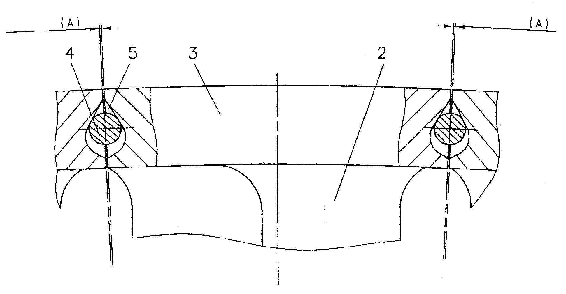
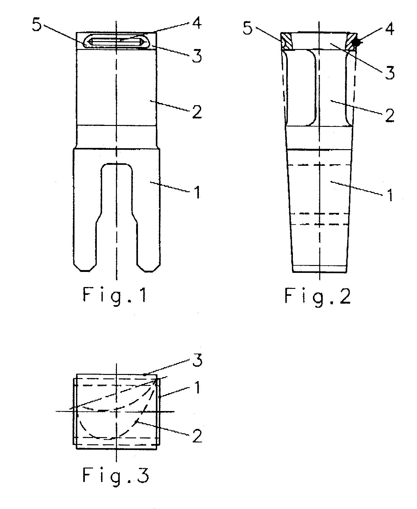
[0037]The rotor blade, which is preferably used in the high-pressure and medium-pressure parts of a turbine, comprises a blade foot 1, which has a conical shape and is designed as a plug-in foot in the case being shown, as well as a streamlined blade leaf 2 and a cover plate 3, which is arranged at the profile end of the blade leaf 2 and lies with its two sloped planes of division on the same radial plane as the two sloped foot surfaces. The cross section of the blade foot 1 and the cover plate 3 is shown as a rectangle in FIG. 3. However, the present invention is equally applicable to rotor blades with a rhomboid cross section.

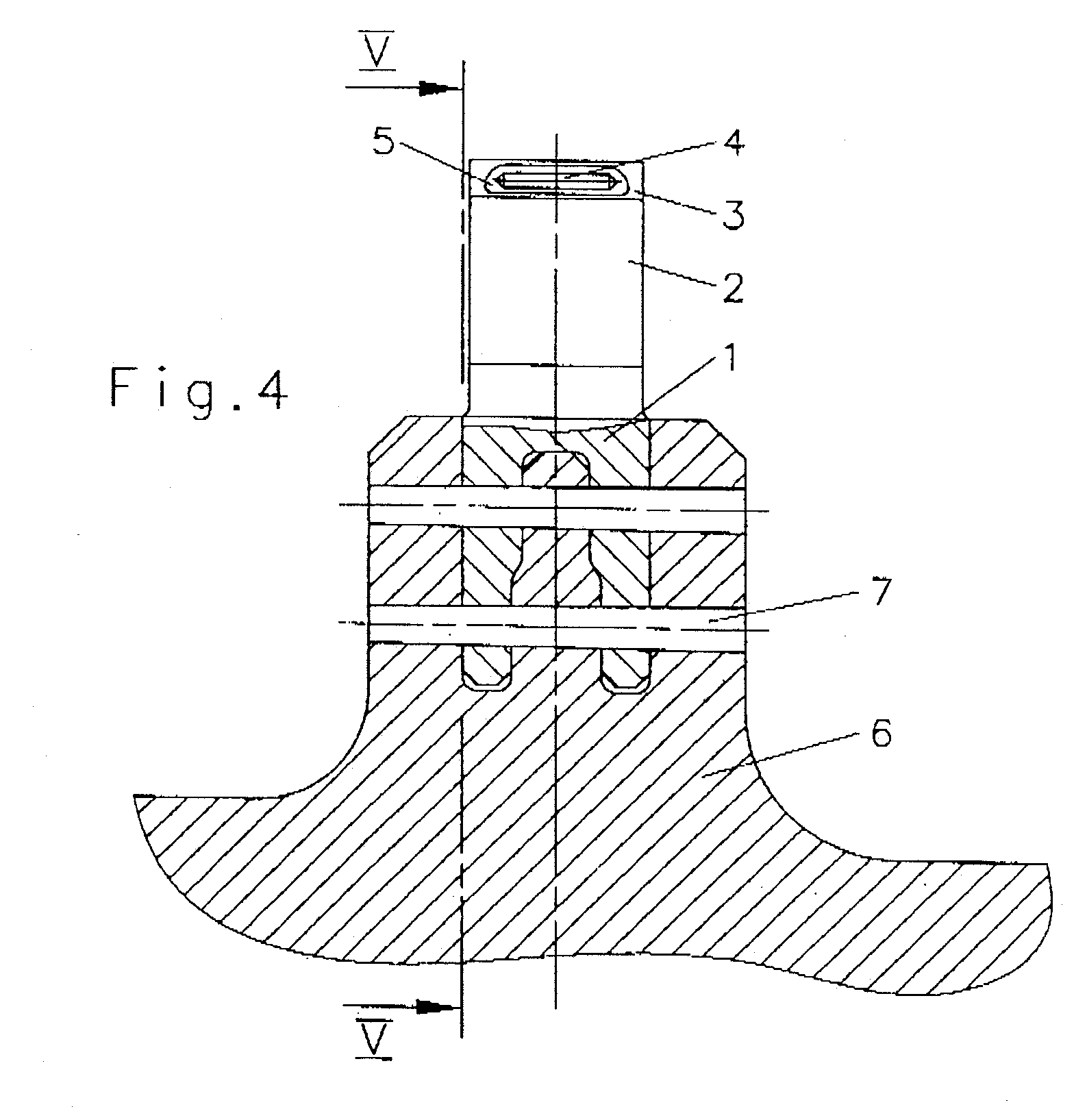
[0038]The blade feet 1 are inserted radially into an adapted circumferential groove of the rotor 6 of the turbine and are held by two conical pins 7 each in the rotor 6 in the case shown in FIG. 4. The shape of the blade feet 1 may also deviate from the view shown and may be, e.g., a simple or double hammer head. The blade feet 1 and the cover plates 3 of the...


PUM


Abstract

A rotor of a steam or gas turbine is equipped with rotor blades, which are held in the rotor (6) in a plurality of radial rows and comprise a blade foot 1 installed in the rotor (6), a blade leaf (2) and a cover plate (3). An open pocket (5) is prepared in the sloping surfaces of the cover plates (3) of a row of rotor blades, which the sloping surfaces are located opposite each other. The pockets (5) of two adjacent cover plates (3) form together an essentially closed cavity, which expands in the radial direction of the rotor (6). A pin, whose largest cross section is smaller than the largest cross section of the cavity but larger than the smallest cross section of the cavity, is placed freely movably into each cavity.

Description

CROSS REFERENCE TO RELATED APPLICATIONS[0001]This application claims the benefit of priority under 35 U.S.C. § 119 of DE 103 40 773.1 filed Sep. 2, 2003, the entire contents of which are incorporated herein by reference.FIELD OF THE INVENTION[0002]The present invention pertains to a rotor of a steam or gas turbine with rotor blades, which are held in the rotor in a plurality of radial rows and each comprise a blade foot installed in the rotor, a blade leaf and a cover plate.BACKGROUND OF THE INVENTION[0003]The following description pertains to the application of the present invention in a steam turbine. The statements made analogously also apply to gas turbines.[0004]Steam turbines are used mainly as powerplant turbines for generating electricity and as industrial turbines for driving generators, pumps, fans and compressors. The steam turbine is a heat engine with rotating rotors, in which the enthalpy gradient of the continuously flowing steam is converted into mechanical energy in...

Claims


Application Information

Patent Timeline
Patent Type & Authority Patents(United States)
IPC IPC(8): F01D5/26F01D5/02F01D5/22F01D5/30
CPCF01D5/225Y10S416/50
Inventor BROCK, HANS-EGONNEUMANN, GUNTERJESKE, HANS
Owner MAN TURBO AG
Why Eureka
Try Eureka