Orthodontic devices for use with arch wires

a technology of orthodontic devices and arch wires, applied in the field of orthodontic devices, can solve the problems of not being able to meet the needs of older patients, not always convenient, and not being able to compromis

Inactive Publication Date: 2006-09-12
AUGUSTA DEV INC
View PDF10 Cites 49 Cited by
  • Summary
  • Abstract
  • Description
  • Claims
  • Application Information

AI Technical Summary

Benefits of technology

[0012]It is another principal object to provide new devices of small size and of an exterior shape that makes them specially suitable for use in lingual techniques, particularly in association with incisor or canine teeth.

Problems solved by technology

This is not always convenient, and may not be possible when the tube is on an intermediate tooth, and the solution is then to use a tube of the so-called convertible type, with which one side of the tube bore can be opened when required for insertion of the wire therein, or its removal.
The compromise is not so suitable for older patients who tend to show their lower teeth more, and in same cases primarily display their lower anterior teeth.
Attempts simply to reduce the size of existing devices are not generally successful, at least partly because changes in scale affects size parameters in different ratios, e.g. areas decrease in square ratio while volumes decrease in cube ratio, with the result That it becomes increasingly difficult, especially with the tiny spring members required, to find materials of the necessary properties.

Method used


Image

  • Orthodontic devices for use with arch wires
  • Orthodontic devices for use with arch wires
  • Orthodontic devices for use with arch wires

Examples


Embodiment Construction

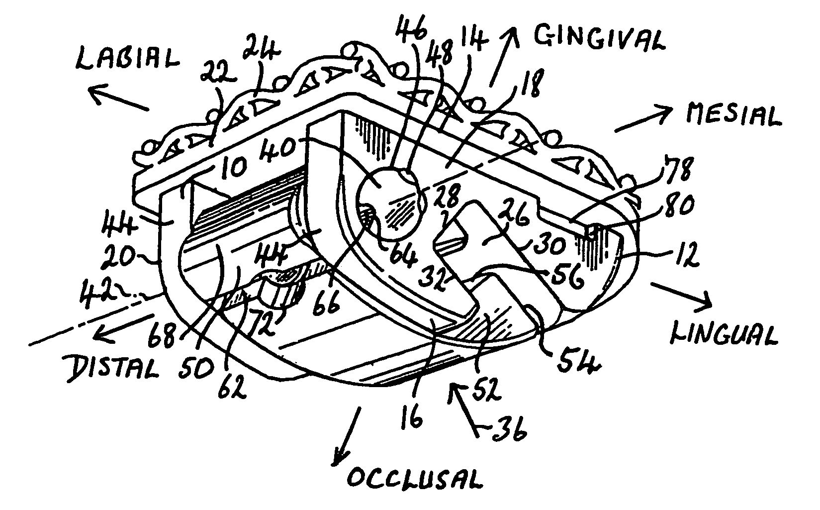
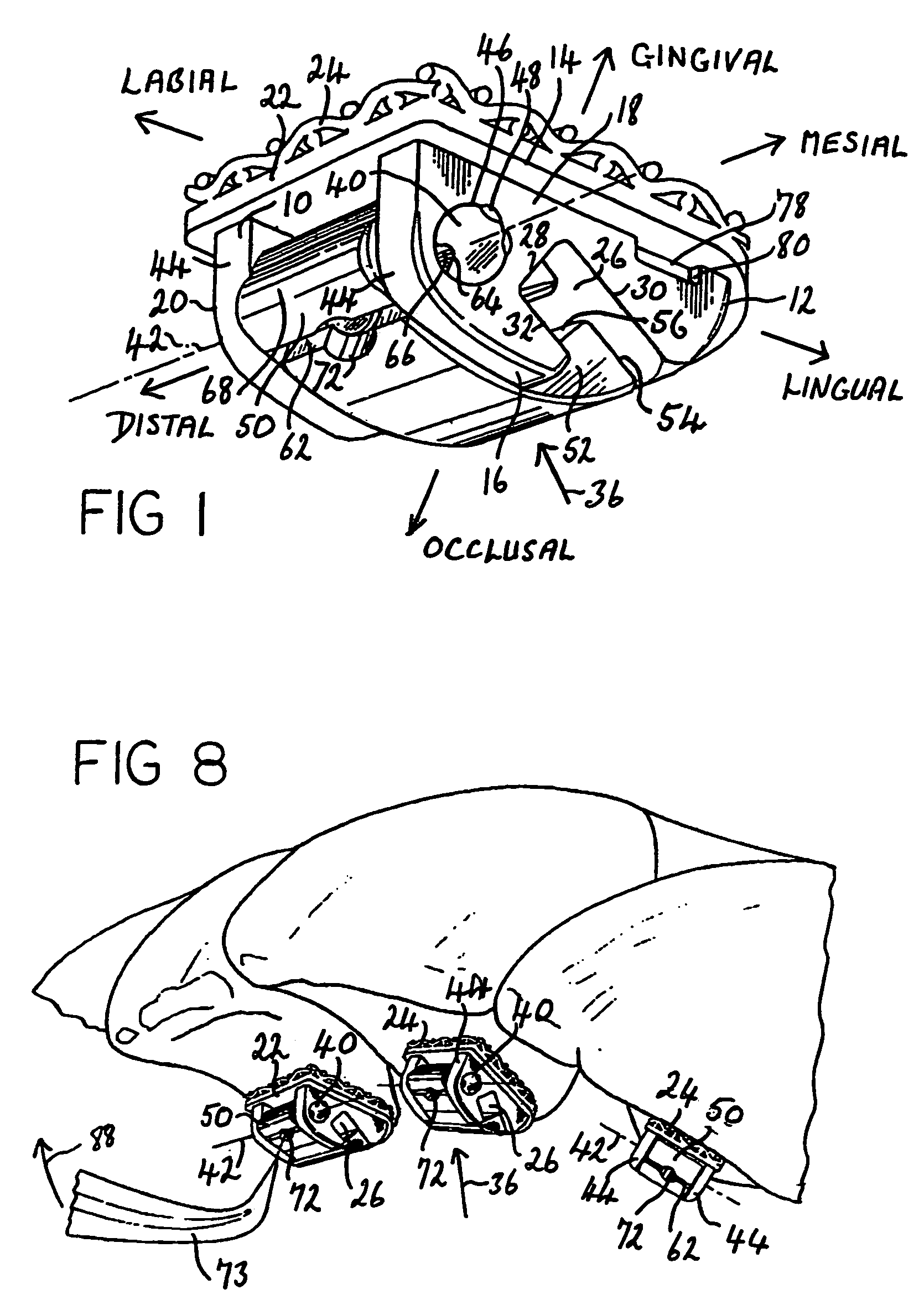
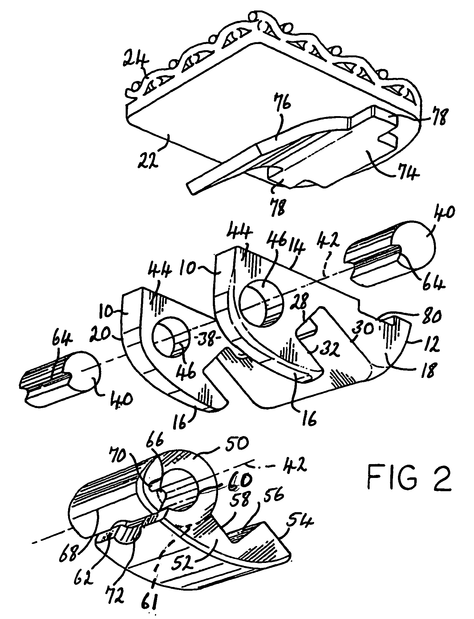
[0045]Similar parts are given the same reference number in all the Figures of the drawings wherever this is appropriate. It may be noted that the devices shown in FIGS. 1 through 11 are intended to be used attached to the lingual surfaces of incisor or canine teeth, while those shown in FIGS. 12–14 are intended to be used attached to the lingual surfaces of bicuspid or molar teeth. FIGS. 19–22 show convertible type orthodontic tubes, that in FIGS. 19 and 20 being active, having an attitude controlling spring therein. while that in FIGS. 21 and 22 Is passive.

[0046]In this specification and the appended claims, for convenience in language the devices and parts thereof are referred to, unless otherwise specified, as they would be used mounted in the upper arch region of a patient's mouth, especially since the brackets described are intended primarily for use in lingual procedures. However, all of the brackets of the invention may be used for either labial or lingual procedures. The lab...


PUM


Abstract

An orthodontic bracket or convertible buccal tube for use with arch wires has the usual mesial distal extending slot having one side open to receive the wire. The open side is closed by a shutter pivoting on a pivot pin, or coaxial pins, about a mesial distal axis, the shutter being latched in slot closed position to retain the arch wire by a latch having one latch member on the pivot pin / s and a cooperating member on an annular part of the shutter surrounding the pin / s. Preferably the latch members are a mesial distal extending cam shaped recess in the pivot pin / s and a projection protruding from the annular shutter part, or vice versa. The part of the annular shutter part carrying the latch member is made flexible by a mesial distal extending through slot dividing it to form a movable segment of about 200° to 270° of the total circumference; a tool can be inserted into the slot to assist in disengaging the latch. The shutter member can have parts thereof that with the shutter in slot closed position are an interference fit against the device body providing an additional retaining force against opening movement. Preferably the device includes an attitude controlling spring member consisting of a thin sheet metal spring within the body having a free end extending into the arch wire slot to engage an arch wire therein, or alternatively consisting of a flexible extension of the part of the shutter member that closes the slot.

Description

CROSS REFERENCE TO A RELATED APPLICATION[0001]This application is a continuation-in-part to my prior application Ser. No. 10 / 623,528, filed 22 Jul. 2003, the priority of which is claimed under 35 USC 120.FIELD OF THE INVENTION[0002]This invention is concerned with improvements in or relating to orthodontic devices consisting of orthodontic brackets and convertible type tubes that are used in orthodontic procedures in cooperation with arch wires, and particularly such devices which have arch wire attitude controlling spring means as a permanent part thereof.BACKGROUND OF THE INVENTION[0003]Orthodontic procedures almost always employ a plurality of orthodontic brackets that are attached to respective teeth, usually by cementing them thereto, although in some circumstances the bracket may still be attached to a metal band which embraces the tooth. Each bracket has a mesial distal extending slot therein, usually of rectangular cross section in a gingival occlusal plane, and the brackets...

Claims


Application Information

Patent Timeline
Patent Type & Authority Patents(United States)
IPC IPC(8): A61C3/00A61C7/28A61C7/30
CPCA61C7/145A61C7/30A61C7/285A61C7/28A61C7/00
Inventor HANSON, G. HERBERT
Owner AUGUSTA DEV INC
Why Eureka
Try Eureka