Lead terminal structure of resolver

Inactive Publication Date: 2006-09-12
MINEBEA CO LTD
View PDF24 Cites 8 Cited by
  • Summary
  • Abstract
  • Description
  • Claims
  • Application Information

AI Technical Summary

Benefits of technology

[0014]Accordingly, it is an object of the present invention to provide a lead wire structure of a hig

Problems solved by technology

In the resolver thus constructed, connecting the lead wire with the coil by soldering has been troublesome, the condition in connecting by the soldering is varied, thereby making the workability and reliability difficult to improve.
Therefore, those members described above can be effectively protected from mechanical damages but not enough

Method used


Image

  • Lead terminal structure of resolver
  • Lead terminal structure of resolver
  • Lead terminal structure of resolver

Examples


Embodiment Construction

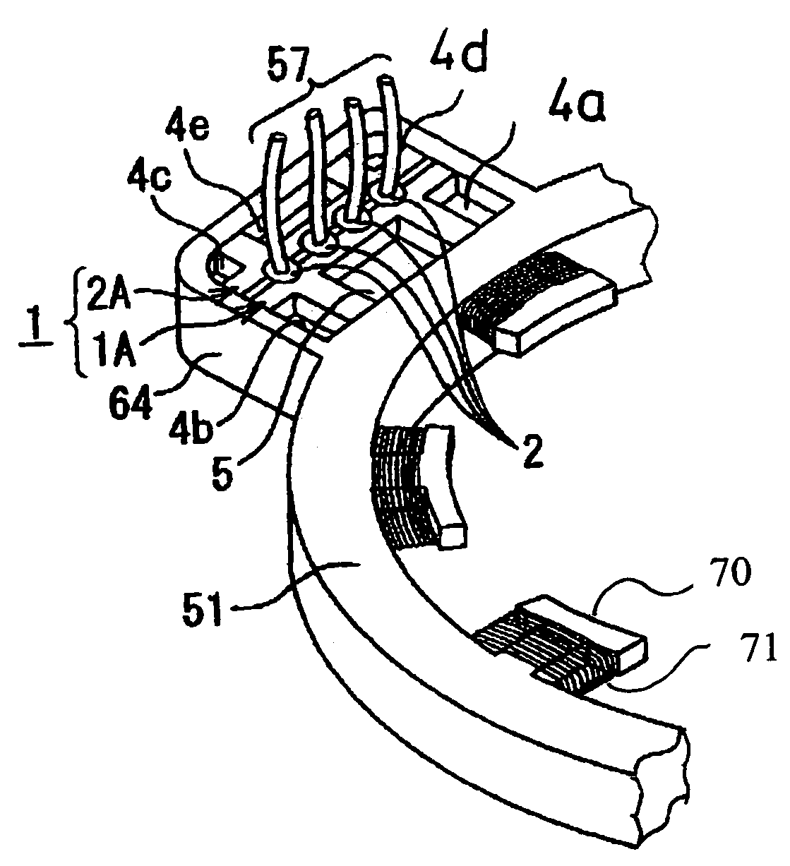
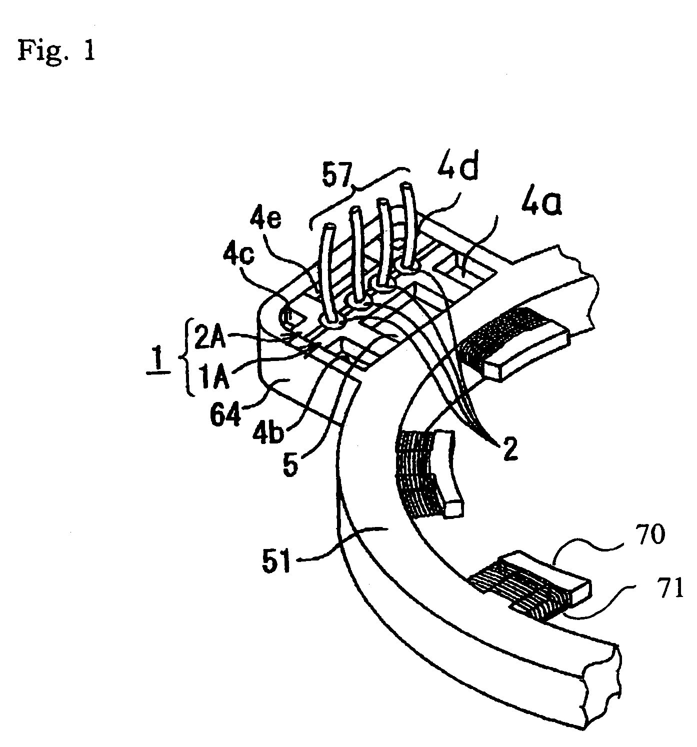
[0032]FIG. 1 is an outward appearance of a lead terminal structure of a resolver of according to an embodiment of the present invention. In FIG. 1, the same portion as in FIGS. 7 and 8 is given the same reference numeral. A stator core 51 is provided with a lead-wire-fixed portion 64, a plurality of fixed pole shoes 70 with a corresponding stator winding 71 wound thereon. The lead-wire-fixed portion 64 is provided with a stator-winding mounting board (shown in FIG. 3). Furthermore, a lead-wire-fixing attachment 1 (1A and 2A) for fixing lead wires 57 is provided in the upper portion of the stator-winding mounting board. The lead wires 57 are put into through-holes 2 provided on the upper end of the lead-wire-fixing attachment 1 (1A and 2A) from the upside and connected to the stator-winding mounting board (shown in FIG. 3). Moreover, the number of lead wires 57 is four and the number of through-holes is also four corresponding thereto, but the number is not limited thereto but may be...


PUM


Abstract

A lead-wire-fixing attachment for fixing a lead wire is provided in a lead-wire-fixed portion arranged in a stator core, and a lead wire is connected to a stator-winding mounting board by way of a through-hole provided at the upper end of the lead-wire-fixing attachment. The through-hole is formed by notches provided at a location where the first attachment and second attachment contact each other. An inlet passage through which a potting material is poured, outlet passages through which the potting material runs out, base portions which are inscribed in the inside wall of the lead-wire-fixed portion are formed in the upper portion of the lead-wire-fixing attachment. The lead wire is made to pass through the through-hole and the lead-wire-fixing attachment is inserted in the lead-wire-fixed portion, and then they are fixed by using a potting material.

Description

BACKGROUND OF THE INVENTION[0001]1. Field of the Invention[0002]The present invention relates to a lead terminal structure of a resolver, particularly a high-quality resolver with improved assembling efficiency so as to enhance a mass productivity.[0003]2. Description of the Related Art[0004]In a conventional resolver, a lead wire is fixed in a slot of a stator core and the end portion of a coil is connected to the lead wire by soldering. In the resolver thus constructed, connecting the lead wire with the coil by soldering has been troublesome, the condition in connecting by the soldering is varied, thereby making the workability and reliability difficult to improve.[0005]For solving the above problems, Japanese Unexamined Patent Publication No. 11-98747 can be shown as one example. Such a lead terminal structure of a resolver is shown in FIG. 7.[0006]In FIG. 7, the entire shape of a stator core 51 is ring-shaped and constructed in a multilayer form, and, for example, a conventional...

Claims


Application Information

Patent Timeline
IPC IPC(8): H02K5/22G01D5/245H02K3/50H02K24/00
CPCH02K3/50
Inventor TETSUKA, TSUNEOAOYAMA, NAOHIKO
Owner MINEBEA CO LTD
Why Eureka
Try Eureka