
Integrated alarm detection and verification device

a verification device and alarm detection technology, applied in the field of security systems, to achieve the effect of reducing the occurrence of false alarms

Active Publication Date: 2006-09-12
ADEMCO INC
View PDF6 Cites 63 Cited by
  • Summary
  • Abstract
  • Description
  • Claims
  • Application Information

AI Technical Summary

Benefits of technology

The present invention is a security system peripheral device that can be mounted in a premises. It includes a primary alarm sensor, an alarm verification unit, and processing circuitry. The primary alarm sensor monitors the protected area and generates an alarm signal when triggered. The alarm verification unit provides verification information to a central station monitor. The processing circuitry generates an alarm enable signal and sends the verification information to the central station monitor. The device also includes a radio frequency (RF) receiver for receiving a danger / duress RF signal from an external RF transmitter. The RF signal causes the processing circuitry to enable the alarm verification unit and transmit the verification information to the central station monitor. The device may also include a secondary alarm sensor that uses a different technology than the primary alarm sensor and has variable sensitivity to reduce false alarms. This dual-technology sensor configuration improves the accuracy and reliability of the security system.

Problems solved by technology

These conditions may include environmental occurrences (e.g. a PIR sensor detects a change in temperature in a protected area that is not due to a person entering it) or they may be due to human error (e.g. a homeowner inadvertently setting off the alarm while in the premises).

Method used


Image

  • Integrated alarm detection and verification device
  • Integrated alarm detection and verification device
  • Integrated alarm detection and verification device

Examples


Embodiment Construction

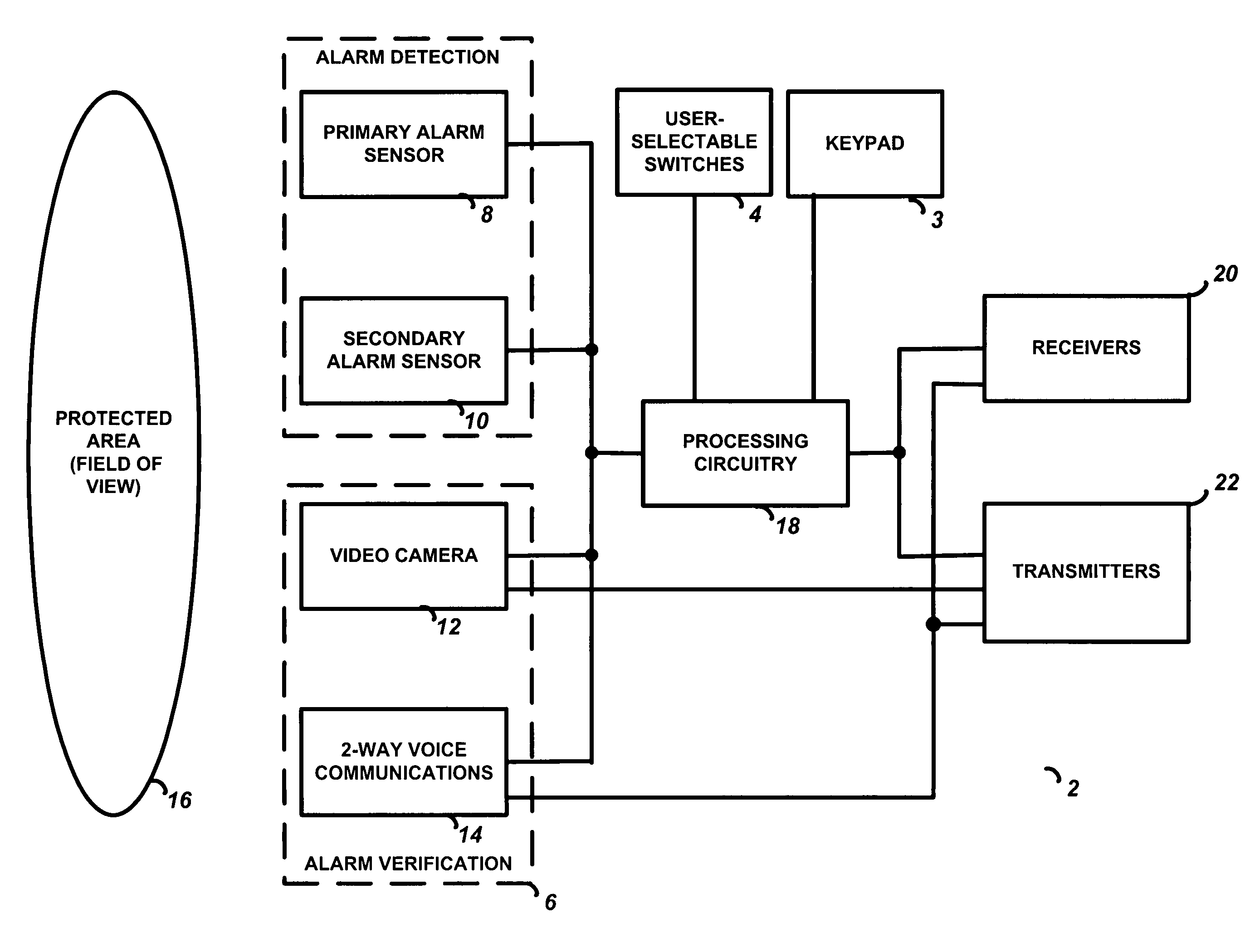
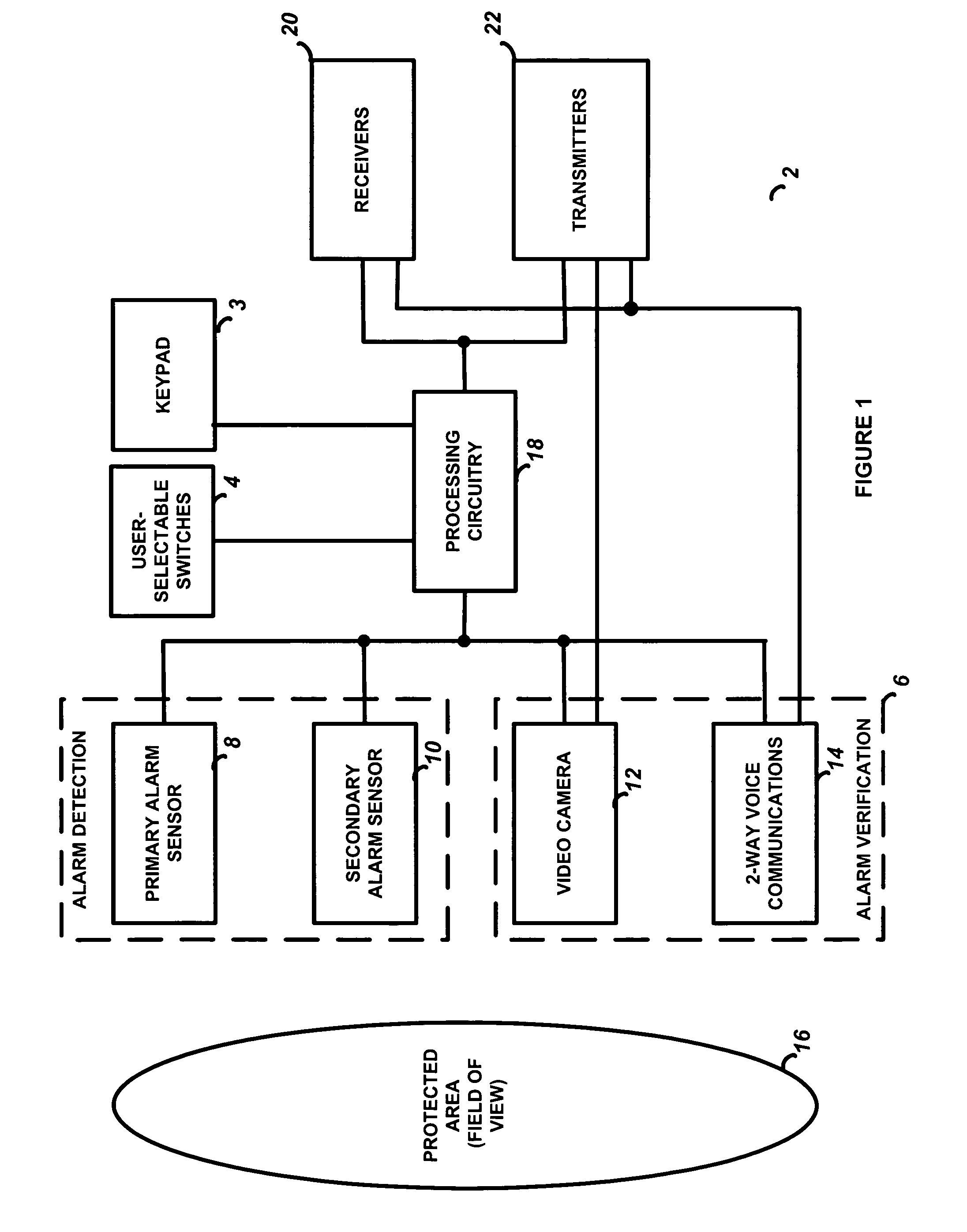
[0018]The preferred embodiment of the present invention is now described with reference to the Figures. FIG. 1 illustrates a basic block diagram of the integrated alarm detection and verification device 2. The device is integrated into a single housing that is located in a premises such as a house or business establishment in order to monitor a certain protected area or field of view, such as a room, a hallway, an entrance foyer, a lobby, an office, a public restroom, etc. Multiple devices 2 may be installed so as to provide contiguous or partially overlapping coverage of multiple protected areas, such as a long hallway, a large room, etc. The specific location of several devices 2 to provide such extended coverage is a function of the range coverage of the specific alarm sensor technologies employed in the device 2 as described below. Such strategic location of alarm sensors is well known in the art and need not be repeated in detail herein.

[0019]The alarm detection and verificatio...


PUM


Abstract

A security system device including a single housing including at least a primary alarm sensor, an alarm verification unit, and processing circuitry. The primary alarm sensor is adapted to monitor a primary protected area and to generate a primary alarm signal when the primary alarm sensor is triggered. The alarm verification unit selectively provides verification information (e.g. video and / or audio signals) from at least part of the primary protected area to a central station monitor. The processing circuitry is adapted to generate an alarm enable signal when the primary alarm signal is generated. On the occurrence of an alarm enable signal, the processing circuitry generates an alarm detected signal and causes the alarm detected signal to be transmitted to a central station monitor, enables operation of the alarm verification unit, and enables transmission of the verification information from the protected area to the central station monitor. A secondary alarm sensor may also be included within the housing, in which case the alarm enable signal is generated only on the triggering of both the primary and secondary alarm sensors. The primary alarm sensor may be adapted to cause the sensitivity of the secondary alarm sensor to be modified on the triggering of the primary alarm sensor.

Description

FIELD OF THE INVENTION[0001]This invention relates to security systems, and in particular to a device that integrates alarm event detection and alarm event verification functions in a single housing.BACKGROUND OF THE INVENTION[0002]Alarm security systems utilize various types of alarm sensor devices mounted in a premises such as a house or business establishment in order to determine if an intruder has breached the premises. As well known in the art, an alarm sensor device will send a signal to a control panel once an intrusion is detected, and the control panel will perform one or more actions, such as sounding a siren and / or transmitting a signal to a central station monitoring service. The central station monitoring service may dispatch security personnel upon receipt of the alarm message from the control panel, for example police or private security personnel may be requested to visit the premises and investigate.[0003]False alarms are sometimes generated by the alarm sensors un...

Claims


Application Information

Patent Timeline
Patent Type & Authority Patents(United States)
IPC IPC(8): G08B13/00G08B25/00G08B29/18
CPCG08B29/183G08B25/00
Inventor KOVACH, JOHN M
Owner ADEMCO INC
Learn More