Speaker and mobile terminal device

a mobile terminal and speaker technology, applied in the field of speakers, can solve the problems of reducing the space available for speakers, unable to obtain sufficient volume of low frequency sound, and unable to achieve sound pressure level, etc., and achieves the effects of generating a loud sound, excellent driving characteristics and acoustic characteristics, and high driving efficiency

Active Publication Date: 2006-09-12
PANASONIC CORP
View PDF16 Cites 52 Cited by
  • Summary
  • Abstract
  • Description
  • Claims
  • Application Information

AI Technical Summary

Benefits of technology

[0044]Thus, the invention described herein makes possible the advantages of providing (1) a compact speaker having a high driving efficiency, which generates a loud sound and has superb driving character

Problems solved by technology

Such an increased size of the liquid crystal display section reduces a space available for a speaker for reproducing a calling sound which is adjacent to the liquid crystal display section.
A simple reduction in size of the diaphragms or magnetic circuit made in accordance with the reduced space for the speaker results in problems, for example, in that a sufficient sound pressure level is not obtained and a sufficient volume of low frequency sound is not obtained.
A speaker having a relatively large speaker diameter of 20 mm provides sufficient acoustic characteristics, but requires a large space to the side of the display section of the cellular phone due to the structure of the cellular phone of outputting the soun

Method used


Image

  • Speaker and mobile terminal device
  • Speaker and mobile terminal device
  • Speaker and mobile terminal device

Examples


example 1

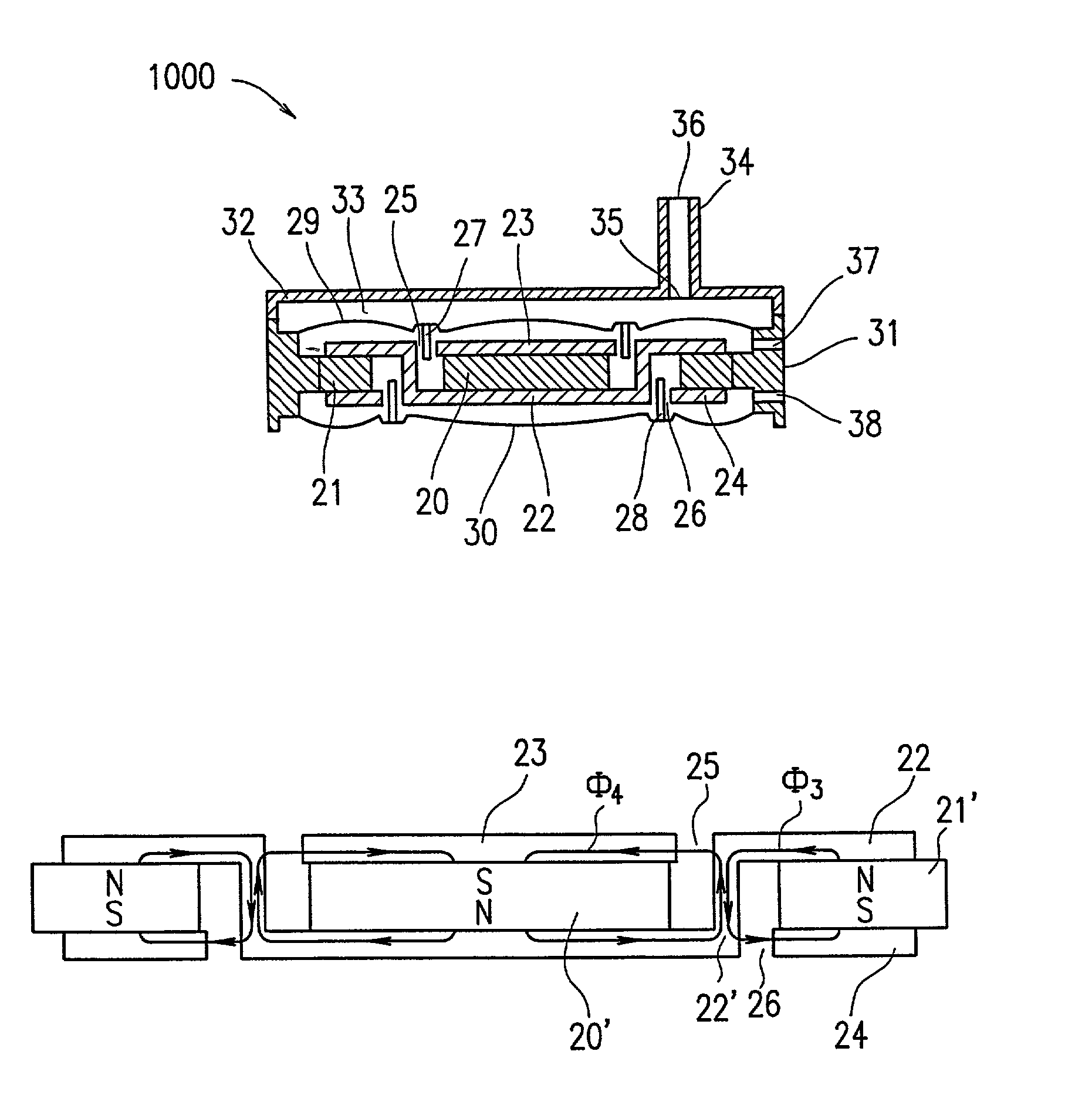
[0081]With reference to FIGS. 1A and 1B, a speaker 1000 according to a first example of the present invention will be described. FIG. 1A is a plan view of the speaker 1000, and FIG. 1B is a cross-sectional view of the speaker 1000 taken along dashed line a–b in FIG. 1A.

[0082]The speaker 1000 includes a cylindrical first magnet 20, an annular second magnet 21 provided so as to surround the first magnet 20, a yoke 22 for integrally connecting the first magnet 20 and the second magnet 21, a first voice coil 27 provided in a first magnetic gap 25 between the first magnet 20 and the yoke 22, a second voice coil 28 provided in a second magnetic gap 26 between the second magnet 21 and the yoke 22, a first diaphragm 29 connected to the first voice coil 27, a second diaphragm 30 oppositely provided to the first diaphragm 29 with respect to the first magnet 20 and connected to the second voice coil 28, a disc-shaped first magnetic plate 23 provided between the first diaphragm 29 and the first...

example 2

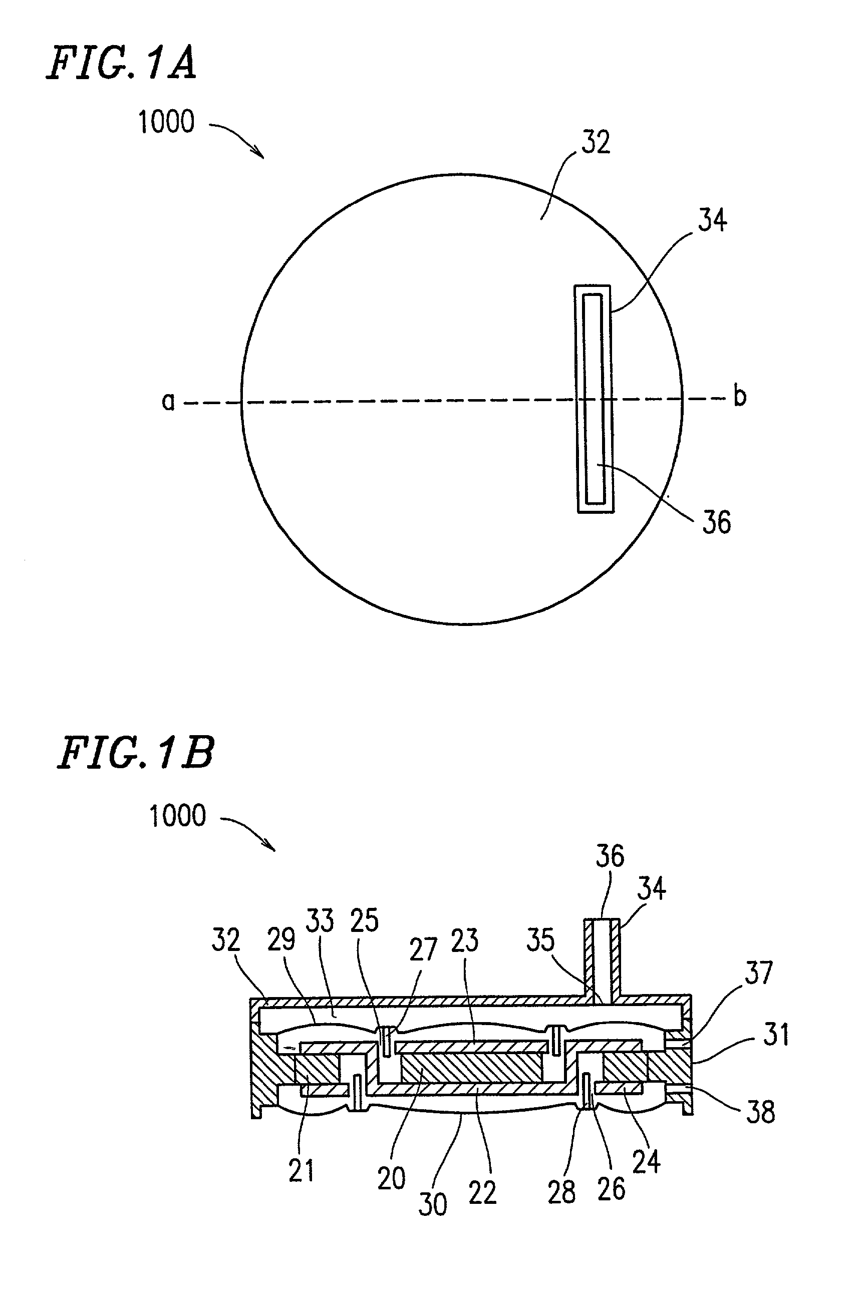
[0093]With reference to FIGS. 2A and 2B, a speaker 1100 according to a second example of the present invention will be described. FIG. 2A is a plan view of the speaker 1100, and FIG. 2B is a cross-sectional view of the speaker 1100 taken along dashed line c–d in FIG. 2A.

[0094]The speaker 1100 includes a yoke 43, an annular magnet 40 provided so as to surround the yoke 43, a first voice coil 48 provided in a first magnetic gap 46 between the yoke 43 and the magnet 40, a second voice coil 49 provided in a second magnetic gap 47 between the yoke 43 and the magnet 40, a first diaphragm 50 connected to the first voice coil 48, a second diaphragm 51 oppositely provided to the first diaphragm 50 with respect to the yoke 43 and connected to the second voice coil 49, a first annular magnetic plate 41 provided between the first diaphragm 50 and the magnet 40, a second annular magnetic plate 42 provided between the second diaphragm 51 and the magnet 40, a non-magnetic connecting member 45 for ...

example 3

[0106]With reference to FIGS. 3A, 3B and 4, a speaker 1200 according to a third example of the present invention will be described. FIG. 3A is a plan view of the speaker 1200, and FIG. 3B is a cross-sectional view of the speaker 1200 taken along dashed line e–f in FIG. 3A. FIG. 4 is a perspective view of a yoke 63 described below.

[0107]The speaker 1200 includes a yoke 63, an annular magnet 60 provided so as to surround the yoke 63, a first voice coil 69 provided in a first magnetic gap 67 between the yoke 63 and the magnet 60, a second voice coil 70 provided in a second magnetic gap 68 between the yoke 63 and the magnet 60, a first diaphragm 71 connected to the first voice coil 69, a second diaphragm 72 oppositely provided to the first diaphragm 71 with respect to the yoke 63 and connected to the second voice coil 70, a first annular magnetic plate 61 provided between the first diaphragm 71 and the magnet 60, a second annular magnetic plate 62 provided between the second diaphragm 7...


PUM


Abstract

A speaker includes a first magnet; a second magnet provided so as to surround the first magnet; a yoke for connecting the first magnet and the second magnet; a first voice coil; a second voice coil; a first diaphragm connected to the first voice coil; a second diaphragm oppositely provided to the first diaphragm with respect to the first magnet and connected to the second voice coil; a first magnetic plate provided between the first diaphragm and the first magnet; and a second magnetic plate provided between the second diaphragm and the first magnet. The first voice coil is provided in a first magnetic gap between the first magnetic plate and the yoke. The second voice coil is provided in a second magnetic gap between the second magnetic plate and the yoke.

Description

BACKGROUND OF THE INVENTION[0001]1. Field of the Invention[0002]The present invention relates to a speaker including a plurality of diaphragms and a mobile terminal device having such a speaker mounted thereon.[0003]2. Description of the Related Art[0004]A speaker including one magnetic circuit and two diaphragms is disclosed in, for example, Japanese Laid-Open Publication No. 62-277000, Japanese Laid-Open Utility Model Publication No. 4-135096, and Japanese Laid-Open Publication No. 11-252683. The speaker disclosed in Japanese Laid-Open Publication No. 11-252683 will be described below.[0005]FIG. 22 is a cross-sectional view of a speaker 3000 disclosed in Japanese Laid-Open Publication No. 11-252683. The speaker 3000 includes a pole piece 1 having a recessed portion which has a hole 14 at a center thereof, a yoke 2 which is recessed at a center thereof and having a hole 13, and a ring-shaped magnet 3 fixed between the pole piece 1 and the yoke 2. The yoke 2 acts as a frame. The spe...

Claims


Application Information

Patent Timeline
IPC IPC(8): H04R25/00H04M1/03H04M1/60H04R1/22H04R9/04
CPCH04M1/03H04R1/025H04R9/045H04R1/225H04M1/6041H04R2499/15H04R2209/026H04R2499/11
Inventor SAIKI, SHUJIUSUKI, SAWAKO
Owner PANASONIC CORP
Why Eureka
Try Eureka